Chapter 2
System Specifications
Environmental Requirements
74
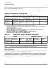
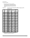
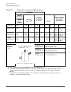
Table 2-17 Physical Environmental Specifications
Condition
Voltage
200–240 Vac
Airflow,
Nominal
b
Airflow,
Maximum
at 32
o
C
a,b
a. Derate maximum dry bulb temperature 1oC/300 m above 900 m.
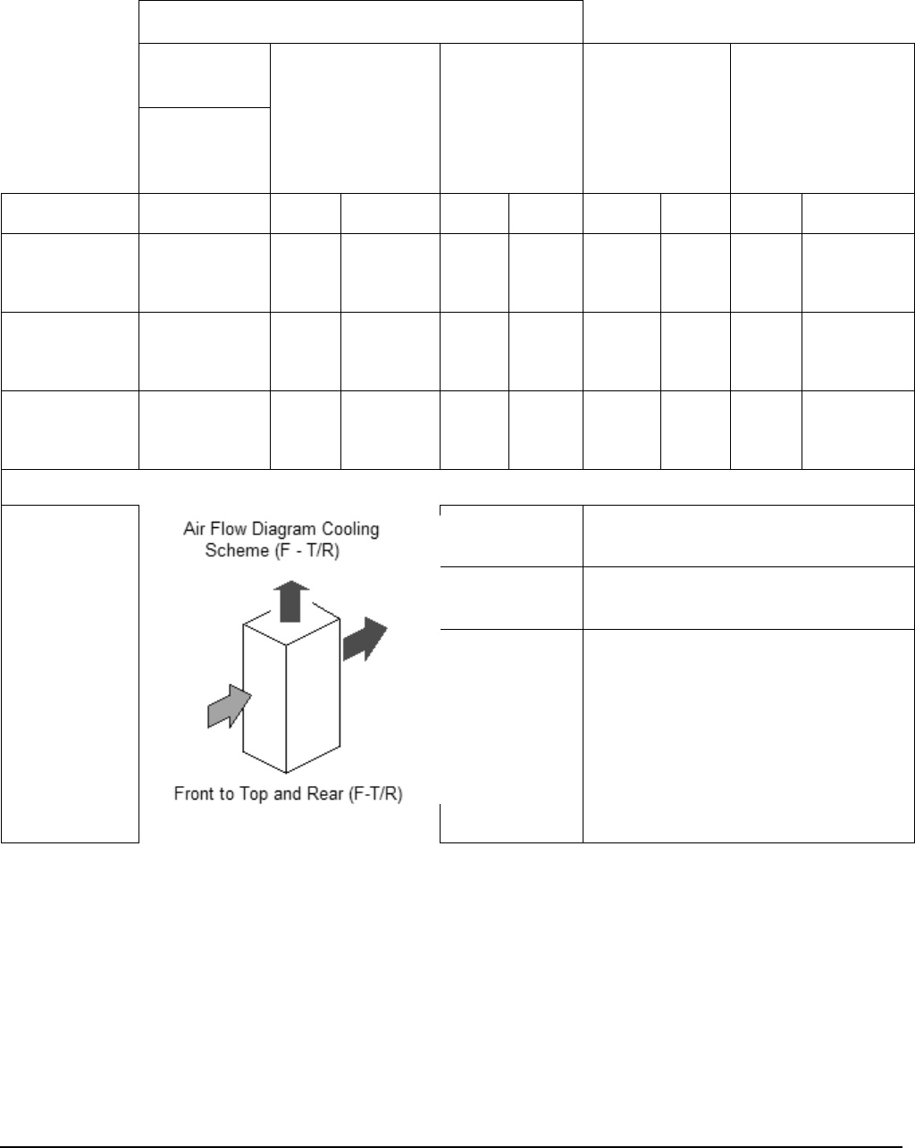
b. The system deviates slightly from front to top and rear airflow protocol. Approximately 5 percent of
the system airflow is drawn in from the rear of the system. See Figure 2-2 on page 73 for more
details.
Weight
Overall System
Dimensions
(W X D X H)
Typical
Heat
Release
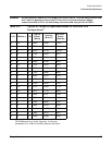
Description Watts CFM
m
3
/hr
CFM
m
3
/hr
lb kg in mm
Minimum
Configuration 3423 2900 5.0 2900 5.0 926.3 420.3 30x48
x77.2
76.2x121.9
x195.6
Maximum
Configuration 9130 2900 5.0 2900 5.0 1241.2 563.2 30x48
x77.2
76.2x121.9
x195.6
Typical
Configuration 6968 2900 5.0 2900 5.0 1135.2 515.1 30x48
x77.2
76.2x121.9
x195.6
ASHRAE
Class
1
Minimum
Configuration
c
c. See Table 2-15 on page 69 and Table 2-16 on page 70 for additional details regarding minimum,
maximum, and typical configurations.
2 Cell, 4 DIMM, 2 I/O
Maximum
Configuration
c
8 Cell, 32 DIMM, 4 I/O
Typical
Configuration
c
6 Cell, 16 DIMM, 4 I/O


