


12-16
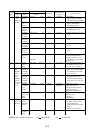
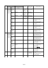
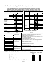
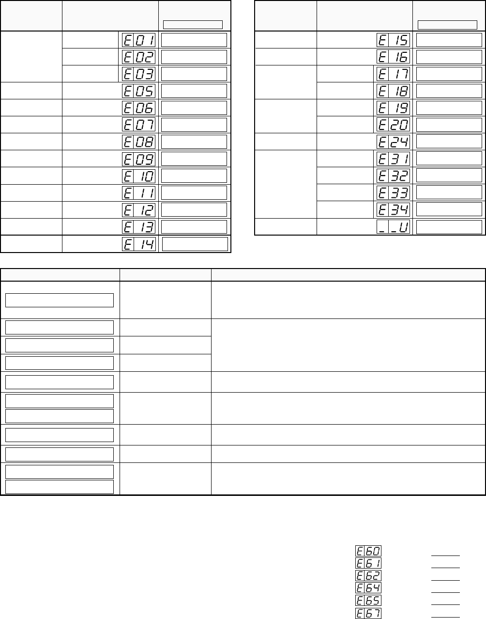
12.4 Protection function display list when the remote operator is used
There are protection functions for overcurrent, overvoltage, and undervoltage provided to
protect the inverter. When one of the functions is performed, the output is cut off, and the
motor is put into the free run state, and the status is kept until the inverter is forced to reset.
Constant speed
Name Digital operator display
Remote operator(DOP)
copy unit(DRW)display
ERR1 ✽ ✽ ✽ ✽
Overload
protection
Name Digital operator display
Remote operator(DOP)
copy unit(DRW)display
ERR1 ✽ ✽ ✽ ✽
Overcurrent
protection
Deceleration
Acceleration
Braking resistor
overload
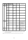
Overvoltage
protection
EEPROM error
Undervoltage
protection
CT error
CPU error
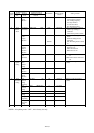
External trip
USP error
Input overvoltage
Instantaneous
power failure
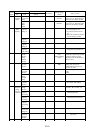
Option connec-
tion error
Option 1
Option 2
Option 1
Option 2
Option PCB
error
(NOTE 2)
Undervoltage
standby
Phase failure
protection error
Power module
protection
Constant speed
Deceleration
Acceleration
OC.Drive
OC.Decel
OC.Accel
Over.L
OL.BRD
Over.V
EEPROM
Under.V
CT
CPU
EXTERNAL
USP
Stop
OV.SRC
Inst.P-F
NG.OP1
NG.OP2
OP1
OP2
UV.WAIT
PH.Fail
PM.Drive
PM.Decel
PM.Accel
PM.ERR
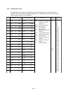
Display
For error contents, see page 8-1.
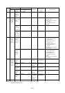
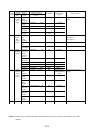
Other displays
DescriptionCause
Communication error
*=1. Protocol error
=2. Time-out error
This is displayed when an error occurs between the inverter and remote operator.
When the STOP key or another key is pressed, the original display appears.
When the original display does not appear, turn the power off and then on once
again. Check whether any connectors are loose.
During inverter running
If one of the displays on the left occurs when the copy unit is used to read or copy,
take the corresponding countermeasure.
• INV. RUN: Stop the running.
• INV. TRIP: Press the STOP key to release the trip.
• INV. TYPE: The inverter type of the copy source is different from that of the
copy destination. Use the same type of inverter to read or copy.
Under inverter trip
Inverter type mismatch
Inverter read lock
The fourth switch of the DIP switch on the back of the remote operator is ON.
When reading data, turn the switch OFF.
Instantaneous power
failure restart function in
operation
This indicates that the instantaneous power failure restart function is being performed.
• RESTART: 0 start is in execution.
• ADJUST: Frequency matching is in execution.
Undervoltage
The supply voltage is lowered to the undervoltage level. When this display
appears, turn the power on once again.
Power OFF The undervoltage after the power is turned off is displayed.
This is displayed after the autotuning measurement is finished.
• Tuning OK: The measurement terminates normally.
• Tuning NG: The measurement fails.
Autotuning function end
display
R-ERROR COMM<
✽
>
R-ERROR INV.RUN
R-ERROR INV.TRIP
R-ERROR INV.TYPE
R-ERROR RD LOCK
RESTART
✽ ✽ ✽
.
✽
s
UV WAIT
POWER OFF
ADJUST
✽ ✽ ✽
.
✽
s
Tuning OK
Tuning NG
(NOTE 1)
Ground fault
protection
GND.Flt
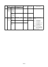
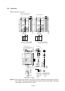
NOTE 1: Power OFF during motor deceleration may cause an input phase failure error.
NOTE 2: When the J-FB is installed, an error is display for each factor as shown below.
Digital operator DOP, DRW
display
Encoder line break:
Overspeed:
Positioning error:
Thermistor line break:
Motor overheat:
Malfunction or abnormality on built-in CPU of the option:
OP1 0
OP1 1
OP1 2
OP1 4
OP1 5
OP1 7