


5-3
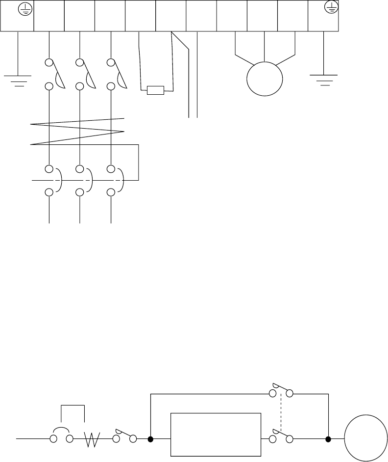
R
(L1)
S
(L2)
T
(L3)
P
(+)
N
(-)
U
(T1)
V
(T2)
W
(T3)
G
(PE)
MOTOR
Braking Units
Power supply
ELB
RB
(RB)
Dynamic
braking
resistor
G
(PE)
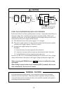
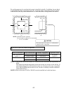
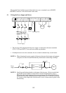
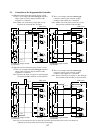
The terminal board will be exposed when the front cover or terminal cover (450L/HF,
550L/HF) is removed. Wire the inverter in this state.
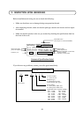
5.1 Wiring the Power Supply and Motor
• The inverter will be damaged if the power supply is connected to the motor terminals
U(T1), V(T2) and W(T3), so be sure not to make any mistakes.
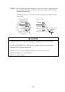
• If multiple motors are to be connected, be sure to attach a thermal relay to each motor.
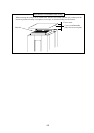
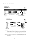
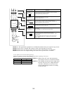
NOTE 1: When changing the power supply of the motor between the inverter and commer-
cial power, be sure to install mechanically interlocked switches Mg1 and Mg2.
Power
supply
ELB
Mg0
R (L1)
S (L2)
T (L3)
(T1) U
(T2) V
(T3) W
Inverter
Mg2
Mg1
Motor
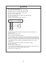
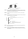
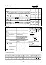
NOTE 2: Install an earth leakage breaker at the input of the inverter. (Select an earth leak-
age breaker whose sensitive current level is raised in high frequency range.)
When the cable length between the inverter and motor is long (more than 10 m),
the thermal relay may malfunction due to higher harmonics. Therefore, install an
AC reactor on the output side of the inverter or use a current sensor in place of the
thermal relay.