


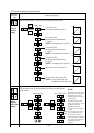
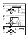
7-18
Contents and display
Extension
function
code
➤
➤
➤
1
2
FUNC
FUNC
.
.
➤
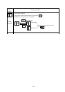
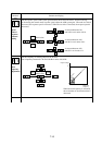
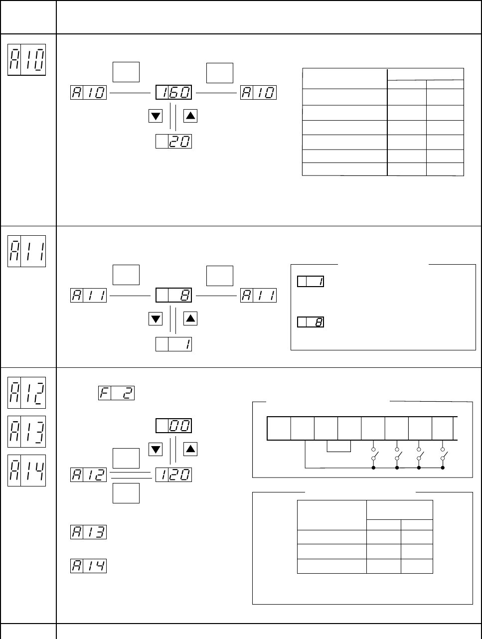
Carrier
frequency
setting
Set the switching frequency of the power module.
Initial value
(NOTE 1)
NOTE 1: The initial value of carrier frequency
varies with the inverter capacity.
When VP1 to VP3 is selected,carrier
frequency is automatically changed to
VT.
Carrier frequency initial value
➤
➤
➤
1
2
FUNC
.
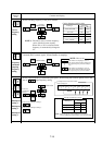
Multispeed
setting 1
Multispeed
setting 2
Multispeed
setting 3
Set the output frequency of each multispeed speed. When setting four or more speeds, refer to the
item of output frequency setting.
Initial value
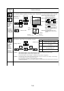
➤
FUNC
FM CM1 PLC P24
(8)
REV
FW
(7)
CF1
(6)
CF2
(7) CF1 (6) CF2
ON OFF
OFF ON
ON ON
(400)
In the case
of multispeed
setting 1
In the case of multispeed setting 2
In the case of multispeed setting 3
Example of the connection method
Refer to Page 5-5
Multispeed
Control circuit
terminal
Multispeed 1
Multispeed 2
Multispeed 3
initial value
16 kHz
model type
055 to 150 L/HF
220 L/HF
300 to 370 L/HF
450 to 550 L/HF
12 kHz
10 kHz
6 kHz
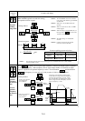
➤
➤
➤
1
2
FUNC
FUNC
➤
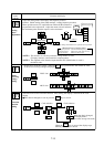
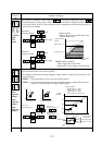
Frequency
command
sampling
frequency
setting
Set the frequency commands (voltage frequency command (O-L terminal signal), current frequency
command (OI-L terminal signal), and the number of samplings.
Initial value
NOTE: How to set
The number of samplings is set to 1.
The reaction time becomes shorter, but
the output frequency becomes likely to
vary.
The number of samplings is set to 8.
The reaction time becomes longer, but
the output frequency becomes stable.
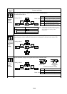
:
:
¥
¥
¥
¥
Example of Multispeed setting
NOTE: When using four or more multispeed commands,
use the multispeed terminal (CF3) as an input terminal.
8 kHz
6 kHz
5 kHz
3 kHz
CT
VT
750 to 1100HF
3 kHz
2 kHz
1320 to 2200HF
2 kHz
2 kHz