


6-3
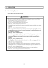
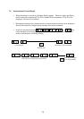
6.2 Test Run
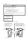
CAUTION
Check the following before and during the test run.
Otherwise, there is a danger of machine breakage.
• Was the direction of the motor correct?
• Was the inverter tripped during acceleration or deceleration?
• Were the SPEED (rpm) and frequency meter correct?
• Were there any abnormal motor vibrations or noise?
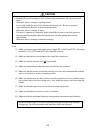
When overcurrent tripping or overvoltage tripping occurs during the test run, increase
the acceleration time or deceleration time.
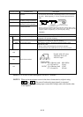
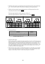
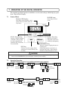
Maximum frequency: 60 Hz
Forward operation
Factory settings
*: For sink type wiring.
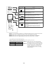
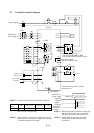
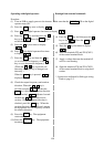
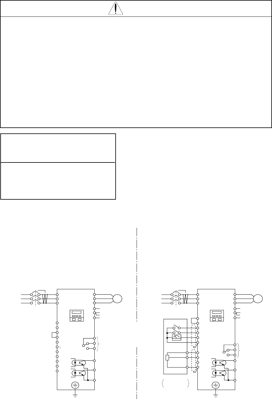
An example of a general connection diagram is shown below.
Operating with digital operator:
When setting frequency, run and stop
with digital operator.
(The same way as remote operator
(DOP) or copy with (DRW).)
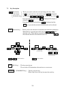
Running from external command:
When setting frequency, run and stop
from external command (FW,RV Terminal.)
The following shows run from
the operation box (OPE-4MJ2,OPE-8MJ2)
(T1)U
(T2)V
(T3)W
RB
(+)
P
FW
CM1
PLC
P24
8
1
H
O
OI
L
Inverter
Ground
Digital
operator
AL
0
AL1
AL
2
11
12
Fault alarm signal
(Normal:
AL0-AL1: ON
Abnormal:
Power off:
AL0-AL1: OFF)
Inverter
Dynamic braking
resistor
Daynamic
braking unit
FW
8
FM
CM1
Operator
OPE-4MJ2
OPE-8MJ2
Frequency meter
Reverse
run/stop
Forward
run/stop
Frequency
setter
Ground
AL
0
AL1
AL
2
Motor
Fault alarm
signal
H
O
OI
L
H
O
L
ELB
L1
L2
L3
R(L1)
S(L2)
T(L3)
ELB
Three
phase
power
supply
L1
L2
L3
Three
phase
power
supply
CM2
(-)
N
PLC
P24
RB
11
12
Dynamic braking
resistor
Daynamic
braking unit
CM2
G
(PE)
(T1)U
(T2)V
(T3)W
(+)
P
R(L1)
S(L2)
T(L3)
(-)
N
G
(PE)
Digital
operator
*
*