


12-3
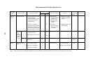
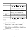
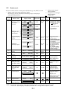
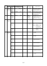
12.2 Monitor mode
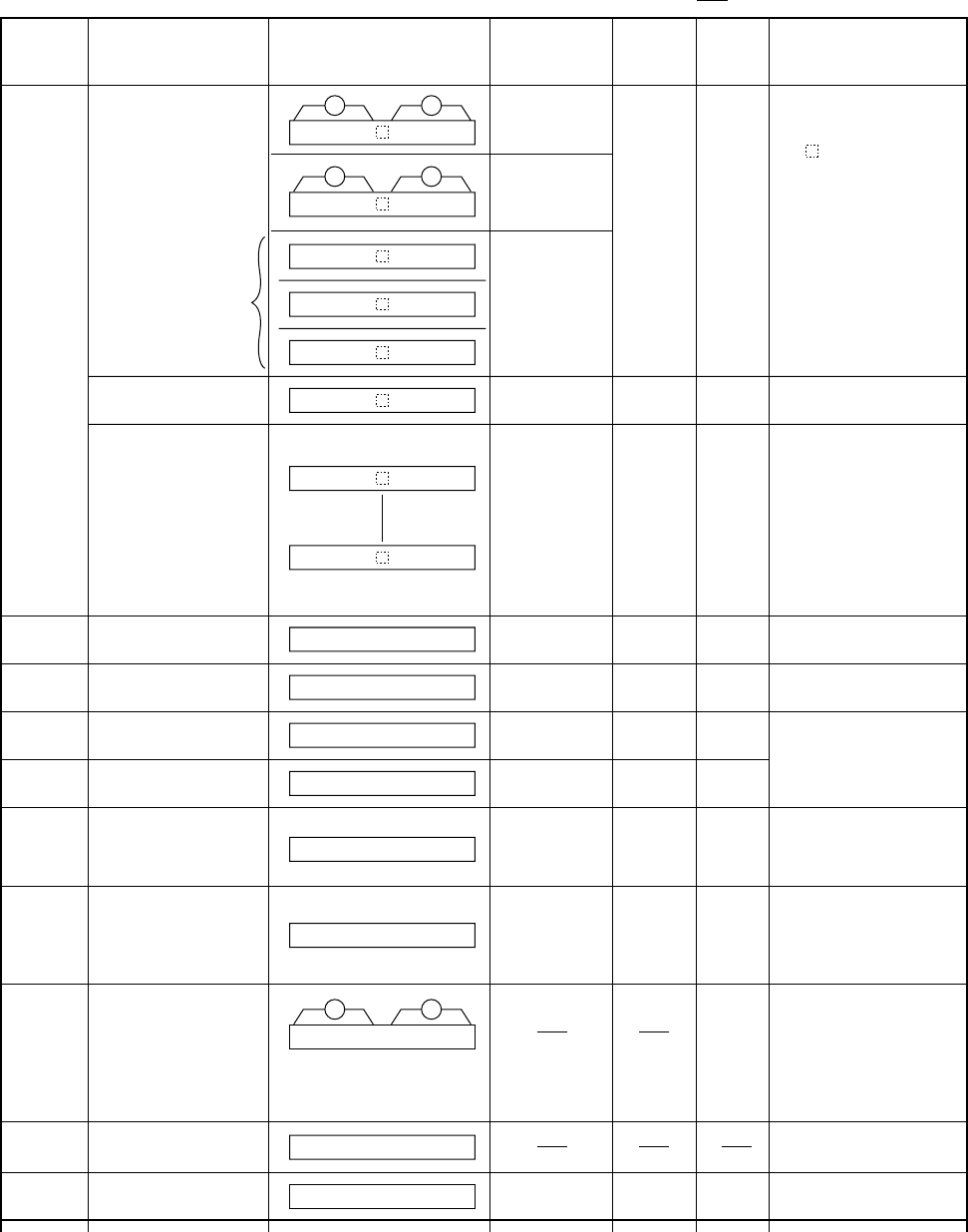
Monitor mode list when the remote operator (DOP) and copy unit (DRW) are used
• Monitor mode initial values and display contents
Initial display contents, initialization, and change ranges are displayed
in the table indicated below.
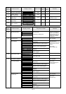
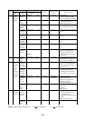
Frequency setting
and output
frequency
Synchronized speed
display
Deceleration time
setting
Acceleration time
setting
: Setting can be changed
during operation
: Setting can not be changed
during operation
: Display only
Y
N
Display
sequence
Monitor name Display content Initial value
Setting
range
Setting and
change are
possible?
Remarks
1
2
3
4
5
6
7
8
9
TRM/REM
OP1/OP2
0.0 Hz
0 to 120
(400)
Y
FS0000.0 0.0Hz
TM 0.0 0.0Hz
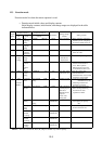
0.0 Hz
Multistage-speed
setting and out-
put frequency
1S0000.0 0.0Hz
0.0 Hz
2S0000.0 0.0Hz
3S0000.0 0.0Hz
Expansion
multistage speed
JG0000.0 0.0Hz
4S0000.0 0.0Hz
7S0000.0 0.0Hz
ACC1 0030.00S
30.0S
0.01 to
3000.00
Y
DEC1 0030.00S
30.0S
Y
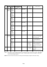
Frequency setting
command
F-SET-SELECT REM
TRM
N
Operation command
F/R-SELECT REM
N
Motor pole count
setting and revolu-
tion speed monitor
RPM 4P 0RPM
4P
2 to 48
Y
Current monitor
/Hz01.0 0.00
(1) displays the setting.
(2) displays the output.
• is displayed
when run
instruction is ON.
F: Forward run
R: Reverse run
REM: Setting from
the remote operator
TRM: Setting from the
inverter terminal
1 2
TRM
1 2
Jogging frequency
setting
A trip occurs easily
at 5 Hz or more.
1.0 Hz
0 to 9.9
Y
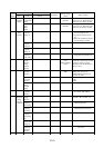
0.0 Hz
0 to 120
(400)
Y
• Valid when the mult-
istage speed terminal
3 is selected.
• The multistage speed
are displayed when
the input terminal is
connected.
• For terminal setting,
refer to F-34 "Input
terminal setting".
0.01 to
3000.00
TRM/REM
OP1/OP2
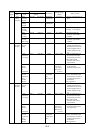
Frequency converted
value setting and
converted value
monitor
The arithmetic value
by the frequency
converted value is
displayed. (NOTE 1)
1.0
0 to 99.9
Y
The (1) section depends
on the INV rated
current.
The (2) section
displays the rate to the
rated output current.
Im 0.0 A 0.0%
Torque monitor
Torque 0%
1 2
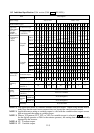
NOTE 1: The terminal output when the digital output frequency monitor is set at the FM terminal of the control
circuit is the "output frequency × frequency converted value". The upper limit of output is 3.6 kHz.
Manual torque
boost adjustment
10
11
0 to 99
Y
V-Boost code <11>