


5-12
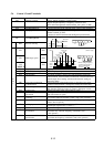
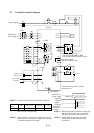
5.6 Control Circuit Terminals
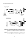
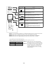
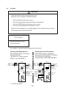
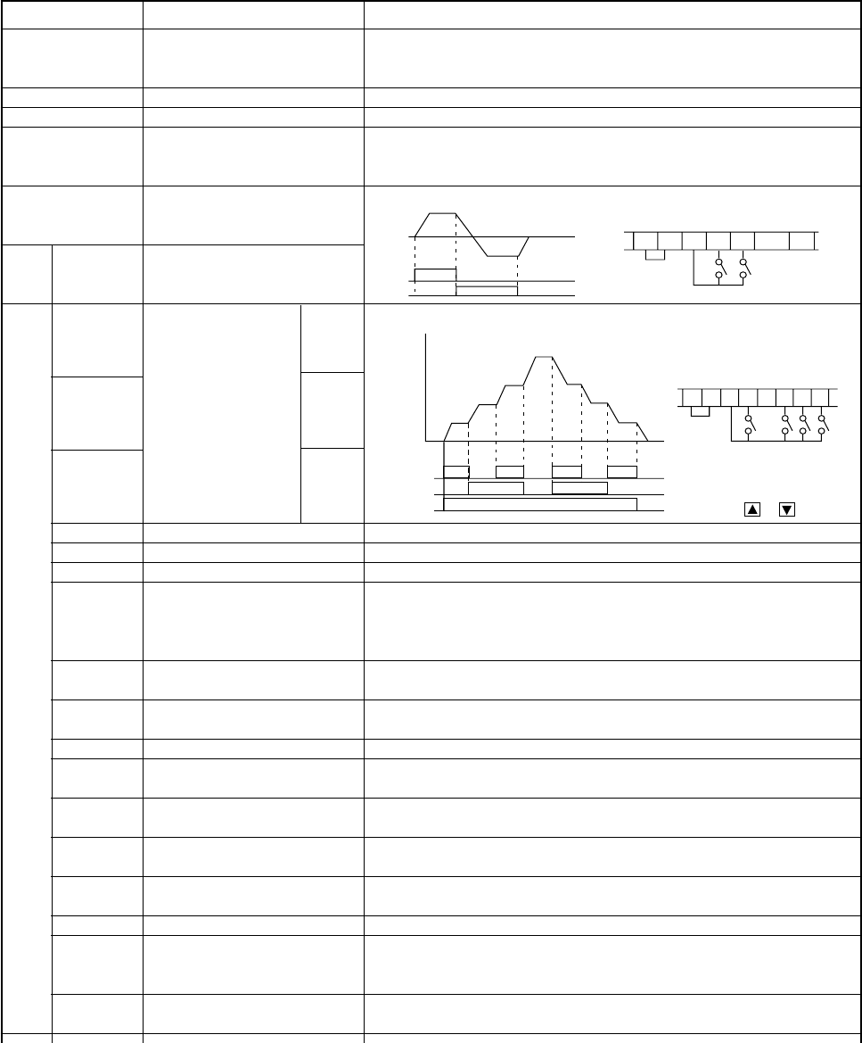
Forward
Reverse
SWF
SWR
ON
ON
SWR
CM1 PLC P24 FW 8 1
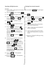
•••••
SWF
ON ON ON ON
ONON
ON
CM1
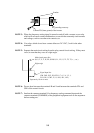
Fourth (FS)
speed
Third
speed
Second
speed
First
speed
Frequency
(Hz)
Switch
SW1
SW2
SWF
Time
PLC P24 FW
876
SWF SW1 SW2
(Source type)
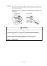
• When setting frequency,
connect P24 and 6 or 7
and set with digital
operator or .
1 2
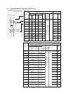
1 to 8
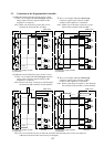
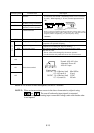
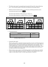
Terminal symbol Terminal name Description
FM Monitor terminal Analog: Output frequency, current, torque
Digital: Output frequency x frequency converted value
(Set in the remote operator monitor mode), max. pulse: 3.6 kHz
CM1 Common terminal 1 Common terminal for the monitor terminal
PLC
Internal interface common
Common terminal for the external power source of the sequencer
P24
Input signal power source
Internal power source for the contact input terminal and frequency
monitor terminal, 24 VDC.
Common for the FW terminal and intelligent input terminals
FW
Forward run/stop terminal
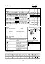
OUTPUT frequency
REV Reverse run/stop
CF1 SW1
CF2 Multistage speed SW2
CF3 SW3
(NOTE 1)
JG Jogging Jogging run
DB External DC braking DC braking input signal
STN Initialization Initialization (shipment status at factory) input
SET 2nd function The output frequency setting, base and maximum frequencies,
control method, motor constant, acceleration or deceleration time,
manual torque boost setting, and electronic thermal setting are
changed in batch.
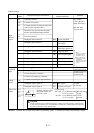
CH1 Two-stage acceleration The acceleration or deceleration time or selection of two-stage
or deceleration accration or deceleration is changed by turning the contact ON.
FRS Free run stop The inverter stops and the motor stops free run
FRS functions when the contact is opened. (European version)
EXT External trip External trip input signal (The contact is open.)
USP Power-ON restart Restart prevention when the power is turned on in the RUN
prevention state (The contact is open.)
CS Commercial power source Switch signal from the commercial power source to inverter
switching drive (Note: When the terminal is used, a trip is also conceled.)
SFT Terminal software lock The data of all funcitons except for output frequency setting is
locked. See 12-9 [F-25].
AT Analog input command Analog input voltage-current switching (When the contact is ON,
current input signal to OI-L is acrive.)
RS Reset Trip or alarm signal is reset.
UP Remote control function, When the contact is turned ON, the operation is accelerated.
acceleration (Available only when the frequency command is sent
to the operator.)
DWN Remote control function, When the contact is turned ON, the operation is decelerated.
deceleration (Available the frequency command is sent to the operator.)