


7-6
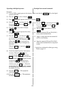
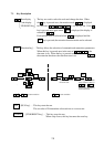
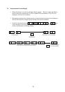
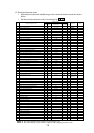
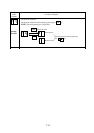
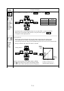
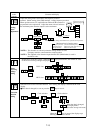
(2) Extension function mode
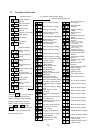
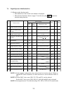
• Each function name and settable range to the extension function mode are shown
below.
• Set the extension function code to be changed by .
NOTE 1: The most applicable motor capacity of the inverter is set.
NOTE 2: The initial setting of each inverter is adjusted when shipping from the works.
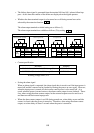
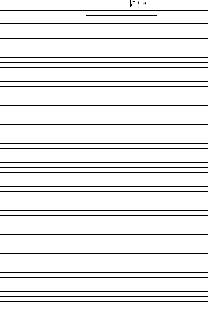
Screen display
Code
display
Setting range Initial value
Remarks
1
2
3
4
5
6
7
8
9
10
11
12
13
14
15
16
17
18
19
20
21
22
23
24
25
26
27
28
29
30
31
32
33
34
35
36
37
38
39
40
41
42
43
44
45
46
47
48
49
50
51
52
53
54
55
56
57
58
59
Control method setting
Motor capacity setting
Motor poles setting
Speed control response constant setting
Start frequency adjustment
Maximum frequency limiter setting
Minimum frequency limiter setting
Jump frequency setting 1
Jump frequency setting 2
Jump frequency setting 3
Carrier frequency setting
Frequency command sampling frequency
Multispeed first speed setting
Multispeed second speed setting
Multispeed third speed setting
Electronic thermal level adjustment
Electronic thermal characteristic selection
Motor pole number setting for motor speed monitor
External frequency setting start
External frequency setting end
Instantaneous restart selection
Dynamic braking usage ratio
Optional arrival frequency for acceleration
Optional arrival frequency for deceleration
Monitor signal selection
Frequency converted value setting
Analog input selection
Frequency arrival signal output method
Restarting after FRS signal selection
Reduced voltage soft start setting
Running mode selection
Jogging freguency setting
Base frequency setting
Maximum frequency setting
Maximum frequency selection
Frequency command/output frequency adjust (O-L terminal)
Frequency command/output frequency adjust (OI-L terminal)
Selection of reset terminal performance
P gain setting of PID funciton
I gain setting of PID funciton
D gain settingof PID function
Selection of PID funciton
Setting method of PID reference value
Setting of PID reference value
Auto tuning setitng
Motor data selection
Ro-To option selection
Input terminal setting 1
Input terminal setting 2
Input terminal setting 3
Input terminal setting 4
Input terminal setting 5
Input terminal setting 6
Input terminal setting 7
Input terminal setting 8
Output terminal setting 11
Output terminal setting 12
Input terminal a and b contact setting
Output terminal a and b contact setting
A 0
A 1
A 2
A 3
A 4
A 5
A 6
A 7
A 8
A 9
A10
A11
A12
A13
A14
A23
A24
A25
A26
A27
A34
A38
A39
A40
A44
A47
A48
A49
A54
A58
A59
A61
A62
A63
A64
A80
A81
A86
A90
A91
A92
A94
A95
A96
A97
A98
A99
C 0
C 1
C 2
C 3
C 4
C 5
C 6
C 7
C10
C11
C20
C21
0-5
3.7 to 160
2/4/6/8
0.00-9.99/10.0-99.9/100
0.10-9.99
0-120 (400)
0-120 (400)
0-400
0-400
0-400
2.0-16.0
1-8
0-120 (400)
0-120 (400)
0-120 (400)
20-120
0-2
2 to 48
0-120 (400)
0-120 (400)
0-3
0.0-99.9/100
0-400
0-400
0-3
0.0-99.9
0-1
0-2
0-1
0-6
0-2
0-9.99
30-120 (400)
30-120 (400)
120/400
0-255
0-255
0, 1
0.1-0.5
0.0-15.0
0.0-100
0-4
0, 1
0.00-200
0-2
0-2
0-1
0-3, 5-9, 11-16, 18-28
0-3, 5-9, 11-16, 18-28
0-3, 5-9, 11-16, 18-28
0-3, 5-9, 11-16, 18-28
0-3, 5-9, 11-16, 18-28
0-3, 5-9, 11-16, 18-28
0-3, 5-9, 11-16, 18-28
0-3, 5-9, 11-16, 18-28
0-2
0-2
00-FF
00-07
0
4
2.00
0.50
0
0
0
0
0
(16.0)
8
0
0
0
100
1
4
0
0
0
(1.5)
0
0
0
1.0
1
0
1
6
0
1.00
60
60
120
Ñ
Ñ
0
1.0
1.0
0.0
0
0
0.00
0
0
0
18
16
5
11
9
13
1
0
0
1
00
04
Externsion function name
Display
order
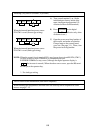
Frequencies below
the start frequency
cannot be set.
Settable
during
running
Ñ
Ñ
Ñ
Ñ
Ñ
Ñ
Ñ
Ñ
Ñ
Ñ
Ñ
Ñ
Ñ
Ñ
Ñ
Ñ
Ñ
Ñ
Ñ
Ñ
Ñ
Ñ
Ñ
Ñ
Ñ
Ñ
Ñ
Ñ
Ñ
Ñ
Ñ
Ñ
Ñ
Ñ
Ñ
Ñ
Ñ
Ñ
Ñ
Ñ
Ñ
Ñ
Ñ
Ñ
Ñ
Ñ
Ñ
Ñ
Ñ
Ñ
Ñ
Ñ
Ñ
Ñ
Ñ
Ñ
Ñ
Ñ
Ñ
NOTE 1
See 7-18
Settable
for
2nd
function
√
√
√
√
Ñ
Ñ
Ñ
Ñ
Ñ
Ñ
Ñ
Ñ
Ñ
Ñ
Ñ
√
√
Ñ
Ñ
Ñ
Ñ
Ñ
Ñ
Ñ
Ñ
Ñ
Ñ
Ñ
Ñ
Ñ
Ñ
Ñ
√
√
Ñ
Ñ
Ñ
Ñ
Ñ
Ñ
Ñ
Ñ
Ñ
Ñ
Ñ
√
Ñ
Ñ
Ñ
Ñ
Ñ
Ñ
Ñ
Ñ
Ñ
Ñ
Ñ
Ñ
Ñ
NOTE 2
See 7-21
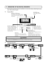
NOTE 2
Set
value