


1-8
CAUTION
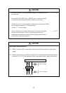
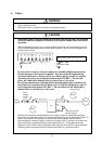
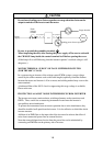
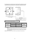
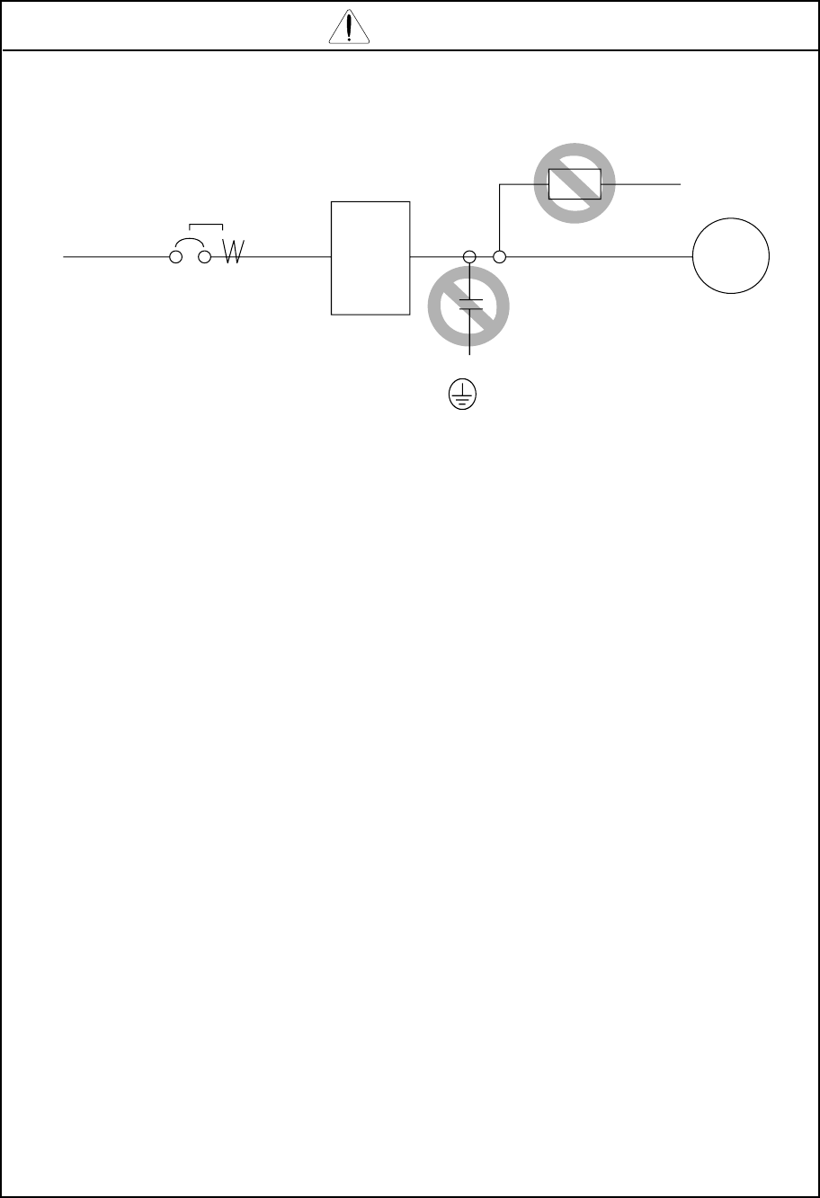
* Do not insert leading power factor capacitors or surge absorbers between the
output terminals of the inverter and the motor.
Earth
leakage
breaker
Power
supply
Surge absorber
Motor
Leading power factor capacitor
INV
(L1)
R,
(L2)
S,
(L3)
T,
(T1)
U,
(T2)
V,
(T3)
W,
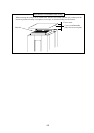
* Be sure to ground the grounding terminal, .
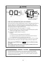
* When inspecting the unit, after turning the power supply off be sure to wait unitl
the CHARGE lamp beside the control terminal is off before opening the cover.
(If the lamp is lit or still flickering, then the internal capacitor’s residual voltage is still
dangerous.)
* MOTOR TERMINAL SURGE VOLTAGE SUPPRESSION FILTER
(FOR THE 400 V CLASS)
In a system using an inverter of the voltage control PWM system, a surge voltage
caused by the cable constants such as the cable length (especially when the distance
between the motor and inverter is 10 m or more) and cabling method may occur at the
motor terminal.
A dedicated filter of the 400 V class for suppressing this surge voltage is available,
Please order one.
* PROTECTION AGAINST NOISE INTERFERENCE FROM INVERTER
The inverter uses many semiconductor switching elements such as transistors and
IGBTs. Thus, a radio set or measuring instrument located near the inverter is
susceptible to noise interference.
To protect the instruments from erroneous operation due to noise interference, they
should be installed well apart from the inverter. It is also effective to shield the whole
inverter structure.
Addition of an EMI filter on the input side of the inverter also reduces the effect of
noise from commercial power line on external devices.
Note that external dispersion of noise from the power line can be minimized by
connecting an EMI filter on the primary side of inverter.