


A-28
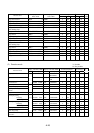
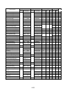
Display with HOP, HRW Display with DOP, DRW
Function No. with digital operator
Data read/copy
Function mode
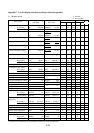
Layer Data display No. Data display
Alterability
No. Data HRW DRW
Deceleration time setting
Firs t setting 3-2-2 1 D1 30.00 s F-07 DEC 1 0030.00 s Y F7 30.0 Y Y
Second setting 1 D1 30.00 s DEC 1 0030.00 s Y F7 30.0 Y N
2-step deceleration time setting 2 D2 15.00 s DEC 2 0015.00 s Y F7 15.0 Y N
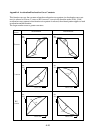
Deceleration time curve pattern selection
3 LINE 0: L DECLINE L N — — Y Y
Acceleration/deceleration curve 4 GAIN 2 DEC GAIN 02 N — — Y Y
constant selection
Acceleration time stop frequency setting
3-3-1 1 F 0.0 Hz F-08 Fsp F 0000.0 Hz N — — Y Y
Acceleration time stop time setting 2 TIME 0.0 s Fsp T IME 00.0 s N — — Y Y
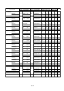
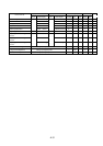
Multi-step speed/process stepping 3-3-2 F-10
selection
Operation mode selection 1 MODE 0: NOR
RUN MODE NOR
Y A59 0 Y N
Free run stop 2 FRS 1: ZST RUN FRS ZST Y A54 01 Y Y
1st speed of Multistage speed 3-3-3 1 S1 0.00 Hz F-11
SPD 1 0000.00 Hz
Y A12 0.0 Y N
2nd speed of Multistage speed 2 S2 0.00 Hz
SPD 2 0000.00 Hz
Y A13 0.0 Y N
3rd speed of Multistage speed 3 S3 0.00 Hz
SPD 3 0000.00 Hz
Y A14 0.0 Y N
4th-7th speed of Multistage speed 4 S4 0.00 Hz
SPD 4 0000.00 Hz
Y F2 0.0 Y N
to to
7 S7 0.00 Hz
SPD 7 0000.00 Hz
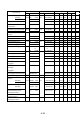
DC braking selection 3-4-1 1 SW 0: OFF F-20 DCB SW OFF N — — Y Y
DC braking type selection 2 KIND 1: LVL DCB KIND LVL N — — Y Y
DC braking frequency selection 3 F 0.5 Hz DCB F 0000.5 Hz — — Y Y
DC braking power selection 4 V-STA 0 DCB V-STA 00 N — — Y Y
(starting time)
DC braking power selection 5 V-STP 0 DCB V-STP 00 N — — Y Y
(stopping time)
DC braking time selection 6 V-STA 0.0 s
DCB V-STA 000.0 s
N——YY
(starting time)
DC braking time selection 7 T-STP 0.0 s
DCB T-STP 000.0 s
N——YY
(stopping time)
DC braking output OFF time adjustment
8 STOP-T 0.00 s
DCB STOP-T 0.00 s
N——YY
Regeneration braking setting 3-4-2 1 %ED 1.5% F21
BRD-%ED 001.5%
Y A38 1.5 Y Y
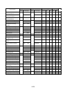
Electronic thermal characteristics
selection
First setting 3-5-1 1 CHAR 1: SUB F23
E-THM CHAR SUB
Y A24 1 Y Y
Second setting 1 CHAR 1: SUB
E-THM CHAR SUB
Y A24 1 Y N
Electronic thermal level setting
First setting 2 LEVEL 100%
E-THM LEVEL 100%
Y A23 100 Y Y
Second setting 2 LEVEL 100%
E-THM LEVEL 100%
Y A23 100 Y N
Electronic thermal characteristics 3 A1 15.8 A
E-THM A1 15.8 A
N——YN
free setting (current value 1)
Electronic thermal characteristics 4 F1 0 Hz
E-THM F1 0000 Hz
N——YN
free setting (frequency 1)
Electronic thermal characteristics 5 A2 15.8 A
E-THM A2 15.8 A
N——YN
free setting (current value 2)
set
value