


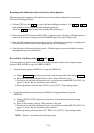
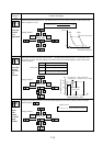
7-22
Contents and display
Extension
function
code
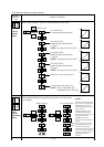
➤
➤
1
2
➤
FUNC
FUNC
➤
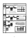
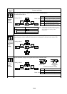
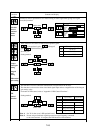
Monitor
signal
selection
Set value
Function
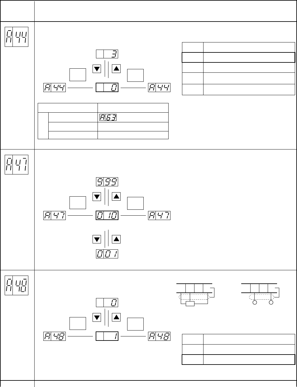
0 Analog output frequency monitor
1 Analog current monitor
2
Analog torque monitor (Note)
Initial value
Setting method
Select the output monitors signal at the control circuit terminal FM from
the table indicated below.
3
Digital output frequency monitor
Initial value
NOTE: Use the analog torque monitor function only in the
sensorless state. Under the V/f control, an appropriate
value is outputted. The accuracy is ±20%
(a rough value).
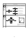
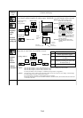
➤
➤
1
2
➤
FUNC
FUNC
➤
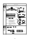
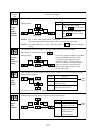
Analog
input
selection
Set value
Function
0 Max. 5 V input
1 Max. 10 V input
Initial value
Setting method
Set the maximum voltage to be supplied between the terminals 0 and L.
Initial value
Input impedance
30 kΩ
Terminal connection example
VR0
(500 Ω to 2kΩ)
DC0 TO 5V
DC0 TO 10V
+Ð
HO01L HO01L
Output monitor signal
Frequency monitor
Current monitor
Torque monitor
Maximum frequency
200% of the rated current
200% of the rated torque
Output full-scale value
Analog
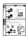
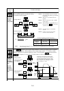
➤
➤
1
2
➤
FUNC
FUNC
➤
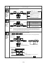
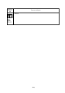
Frequency
converted
value
setting
Initial value
Setting method
Set a converted value for frequency converted value monitoring. The product of this setting and the
ouptut frequency (d0) is displayed as the value for the frequency converted value monitor (d3).
➤
➤
1
2
.
.
.