


9-3
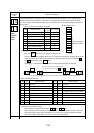
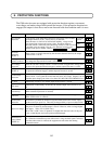
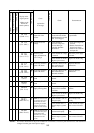
Symptom
Circuit breaker (MCB)
Electromagnetic contactor (Mg)
Thermal relay (THRY)
Failure alarm relay
Display on the
digital operator
(display on the
LCD of the
remote operator)
How to reset
Cause
(explanation
of message)
Check Countermeasure
Ground fault on the
output side of the
inverter
Excessive received
voltage
Defective power
supply (instantaneous
power outage)
Incorrectly connected
option-1 PC board
Incorrectly connected
option-2 PC board
Defective option-1 PC
board
Defective option-2 PC
board
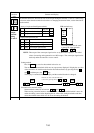
Defective power
supply (missing phase)
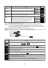
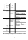
(NOTE 1) Failure detected
by a detector in the power
module while the motor
was running at a constant
speed, or excessive tem-
perature rise in the inverter
(NOTE 1) Failure detected
by a detector in the power
module during motor
deceleration, or excessive
temperature rise in the
inverter
Check the wiring between the
inverter and motor and also
check the motor for a ground
fault. (Use a megger.)
Check whether an
excessive voltage was
received during an
operation other than
deceleration.
Check whether the voltage
is lowered.
Check whether the MCB or
Mg has a poor contact.
Check the connectors and
other connections for
abnormal conditions.
Check the connectors and
other connections for
abnormal conditions.
Refer to the instruction
manual.
Refer to the instruction
manual.
Check the power supply
connections for abnormal
conditions.
Check whether the MCB or
Mg has a poor contact.
Check whether a load was
changed rapidly.
Check whether there is a
shorted output or ground
fault.
Check whether the speed
was decreased rapidly.
Check whether there is a
shorted output or ground
fault.
Correct the portions having
a ground fault.
•
Lower the voltage to be
received.
•
Reduces fluctuations of
the received voltage.
•
Install an AC reactor on
the input side.
Restore the power supply
to normal.
Replace the MCB or Mg.
Repair the defective
connections.
Repair the defective
connections.
Repair the abnormal
portions.
Replace the MCB or Mg.
Do not change loads
rapidly.
Check whether the output
lines or motor is shorted.
Set a longer deceleration
time.
Check whether the output
lines or motor is shorted.
A
A
A
A
A
A
A
A
A
A
●
●
●
●
●
●
●
●
●
●
E14
(GND. Flt)
E15
(OV. SRC)
E16
(Inst. P-F)
E17
(NG. OP1)
E18
(NG. OP2)
E19
(OP1)
E20
(OP2)
E24
(PH. Fail)
E31
(PM. Drive)
E32
(PM. Decel)
NOTE 1: The failures detectable in the power module are overcurrents, excessively hot main devices, and insufficient
voltages from the gate circuit power supply.