


5-10
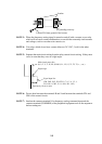
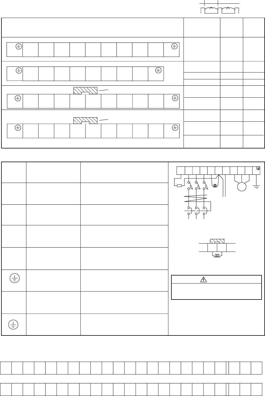
5.5 Terminal
➤
➤
Terminal layout
Main power
Type
Width
(mm)
Screw
diameter
Inverter output
External braking
resistor
Dynamic braking unit
Ground
Connect the power supply
Connect the motor
Connect a braking resistor (option)
Connect a dynamic braking unit
(option)
Ground (connect grounding to avoid
electric shock)
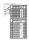
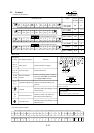
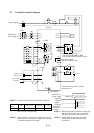
Terminal description
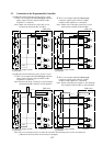
(1) Main circuit terminal
Width
S
(L2)
R
(L1)
T
(L3)
P
(+)
N
(Ð)
U
(T1)
V
(T1)
W
(T1)
G
(PE)
R
(L1)
G
(PE)
S
(L2)
T
(L3)
PD
(+1)
P
(+)
N
(Ð)
U
(T1)
V
(T1)
W
(T1)
G
(PE)
055, 075LF
055,075HF
011, 150HF
220 to 370HF
450, 550HF
M6
17.5
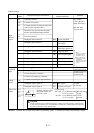
Main circuit
Function
Terminal
symbol
R, S, T
(L1),(L2),(L3)
U, V, W
(T1),(T2),(T3)
P, RB
(+),(RB)
P, N
(+),(-)
G
(PE)
* Only the 055LF/HF and 075LF/HF
are equipped RB terminals .
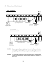
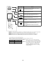
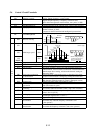
(2) Control circuit terminal
The intelligent I/O terminals 1 to 8 and 11 and 12 are initialized as shown below at factory before shipment.
FM CM1 PLC P24 FW REV CF1 USP CH1 FRS JG AT RS H O OI L CM2 RUN FA1 AL2 AL1 AL0
FMCM1PLCP24FW87654321HOOILCM21211AL2AL1AL0
↑↑ ↑↑↑↑↑↑ ↑↑
R
(L1)
G
(PE)
S
(L2)
T
(L3)
PD
(+1)
P
(+)
N
(Ð)
U
(T1)
V
(T1)
W
(T1)
G
(PE)
750, 900HF
1100HF
M10
M10 40
35
Internal short circuit bar
Internal short circuit bar
M8 23
R
(L1)
S
(L2)
T
(L3)
PD
(+1)
P
(+)
N
(-)
U
(T1)
V
(T2)
W
(T3)
G
(PE)
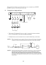
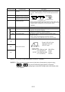
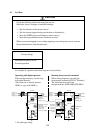
MOTOR
DCL
Braking Units
Power supply
ELB
RB
(RB)
Braking
resistor
PD
(+1)
P
(+)
Internal short circuit bar
DCL
Remove the internal short circuit bar when
DCL is connected.
External choke coil
Ground at case
Connect a choke coil (DCL) for
harmonics current reduction
Ground (connect grounding to avoid
electric shock)
PD
(+1)
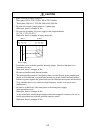
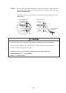
WARNING
Wait until DC bus voltage is discharged after power
supply is turned off.
Otherwise, there is a danger of electric shock.
M5
M6
17.5
13
G
(PE)
RB
(RB)
S
(L2)
R
(L1)
T
(L3)
P
(+)
N
(Ð)
U
(T1)
V
(T1)
W
(T1)
G
(PE)
G
(PE)
011, 150LF
220 to 370LF
450, 550LF
M8 23
M10
35
1320 to 2200HF M16 51