


A-33
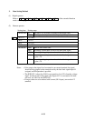
3. Data Setting Method
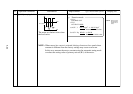
(1) Digital operator
Refer to
90
A
91
A
92
A
94
A
95
A
96
A
of the extended funciton
mode contents (pages 7-26 and 7-27).
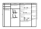
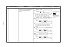
(2) Remote operator
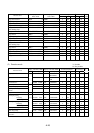
Setting item Setting range
PID IN-SEL IN The PID LVL set value is assumed as the target value.
OUT The target value depends on the frequency setting method.
PID LVL 0 to 200%
PID P 0 to 5.0
PID I 0 to 15.0
PID D 0 to 100.0
PID MODE MD0 Built-in PID control OFF
MD1 An analog current input is used as the feed-back signal.
MD2 An analog voltage input is used as the feed-back signal.
MD3 An analog current input is used as the feed-back signal.
I gain
×
10.
MD4 An analog voltage input is used as the feed-back signal.
I gain
×
10.
43F
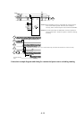
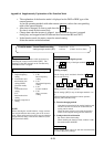
Notes: • If the target value signal is to be entered to an external terminal, the signal
should not be assigned to the terminal used by the feed-back signal input. If
assigned, no PID operation is possible.
• The [PID LVL] value (0 to 200%) corresponds to 0 to 10V of analog voltage
input. In other words, if the target value input of 5V is converted to an inter-
nal level, set 100% for the [PID LVL].
• If target values are to be entered with current (OI-L input), turn on the AT
terminal.