


7-13
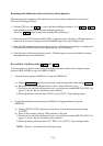
Contents and display
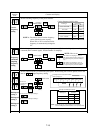
Monitor
mode
contents
➤
➤
➤
➤
1
2
➤
1
2
FUNC
FUNC
➤
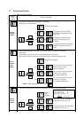
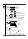
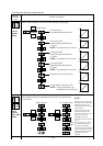
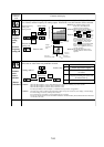
Analog
meter
adjustment
FM
CM1
PLC
P24
Adjust the analog meter connected to the frequency monitor
terminal. (Initial setting of the [FM] terminal: Analog frequency monitor)
When operation starts, t/T output between FM and CM1 terminals is
proportional to the output data. Adjust the meter so that it indicates
the maximum point when the output is at the maximum.
Initial value
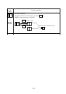
When adjusting the analog meter furthermore, repeat the same operation.
Maximum level of analog meter
Frequency monitor:
Current monitor:
Torque monitor:
(A63 maximum frequency setting)
(200% of inverter rated current)
(200% of rated torque)
NOTE 1:
NOTE 2:
This function is valid only when the analog monitor is used.
(Freqency monitor, current monitor, torque monitor)
The adjusted value when the input terminal STN (initialization) is used is
the initial value.
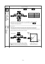
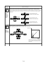
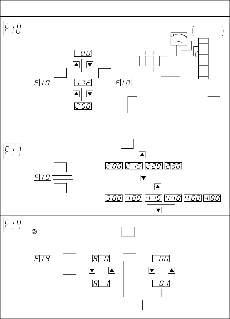
Motor
receiving
voltage
setting
➤
FUNC
➤
FUNC
➤
1
➤
2
400 V class
Initial value
Set the motor receiving voltage. When the key is pressed once, the current set value
of the motor receiving voltage is displayed.
FUNC
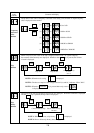
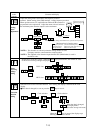
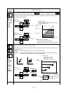
Extension
function
setting
➤
FUNC
➤
FUNC
Select the item of each extension function. After setting, the display is returned to the code
display.
After data is changed, be sure to press the key to store it.
➤
➤
2
1
➤
FUNC
➤
➤
2
1
➤
Code selection
When the data is changed,
the display blinks.
(Set value storage wait state)
Code selection
When the key is pressed, the display stops
blinking and the data is stored.
FUNC
FUNC
Sink type wiring
Refer to page 5-3
➤
➤
➤
➤
t
T
Output =
t (variation)
T
➤
1
➤
2
200 V class
Initial value