


10-2
NOTE 1: If the inverter is used under high temperature and heavy load conditions, its operat-
ing life will be significantly reduced.
NOTE 2: If the inverter has been stored for three years or more, apply the following condi-
tions.
1) Apply 80% of the rated voltage of the capacitor for 1 hour at normal tempera-
ture.
2) Increase the voltage to 90% and apply it for 1 hour.
3) Apply the rated voltage for 5 hours.
NOTE 3: Precautions in handling printed-circuit boards.
When maintenance and inspection of printed-circuit boards is necessary, be sure to
follow the precautions below.
• Prevent damage caused by static electricity. The IGBT of the inverter module,
the MCUs and ICs on a printed-circuit board can be destroyed by static electric-
ity, so be sure to ground work benches, soldering irons, and yourself before
working on a printed-circuit board.
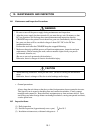
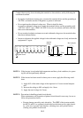
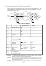
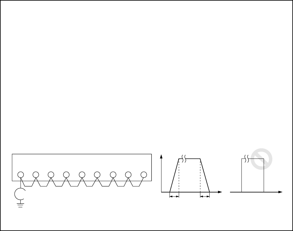
Conduct these tests by short-circuiting the terminals as shown below, and by following the
conditions described.
• In regard to insulation resistance tests, measure the terminals below and the grounding at
500 VDC, and make sure that 5 Megohms or greater is indicated.
• Do not perform the withstand voltage test. When it should be done,
in regard to withstand voltage tests, supply the terminals below and the grounding with
1500 VAC (200 V class), 2000 VAC (400 V class) for one minute, and make sure that
there are no abnormalities.
• Do not conduct insulation resistance tests and withstand voltage tests for terminals other
than those indicated below.
• Increase or decrease the applied voltage for the withstand voltage test slowly and turn the
equipment 0 V again.
Megohm-meter
R
N
P
Time Time
0.1 sec. or more 0.1 sec. or more
A
pp
li
e
d
voltage
RBST UVW
(L1) (L2) (L3) (RB) (+) (-) (T1) (T2) (T3)
Good example
Bad example