


5-7
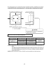
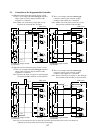
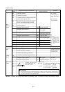
5.3 Connection to the Programmable Controller
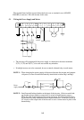
(1) When the internal interface power source is used
① This is an example when the sink type transistor
output (open collector output) module of the
sequencer is connected
② This is an example when the source type
transistor output (open collector output)
module of the sequencer is connected
Note:
Make sure of the short-circuit bar or wire
between the terminals PLC and P24.
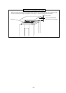
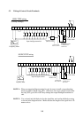
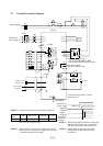
(2) When the external interface power source is used
① This is an example when the sink type transistor
output (open collector output) module of the
sequencer is connected
② This is an example when the source type
transistor output (open collector output)
module of the sequencer is connected
Note:
Remove the short-circuit bar or wire between
the terminals CM1 and PLC or P24 and PLC.
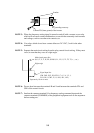
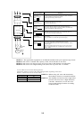
Note: Remove the short-circuit bar or wire between
the terminals CM1 and PLC or P24 and PLC.
J300 series J300 series
J300 series J300 series
YTR48 type output module
(by Hitachi)
YTS48 type output module
(by Hitachi)
Inverter Inverter
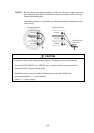
Note: Be sure to turn the inverter on after the controller and external power source are turned on.
(Otherwise, the data in the inverter may be changed.)
YTR48 type output module
(by Hitachi)
YTS48 type output module
(by Hitachi)
S
1
2
8
9
8
2
1
FW
PLC
CM1
P24
COM
24V DC
+
-
COM
1
2
8
9
8
2
1
FW
PLC
CM1
P24
24V DC
+
-
S
S
1
2
8
9
8
2
1
FW
PLC
CM1
P24
COM
24V DC
+
-
24V DC
+
-
24V DC
+
-
8
2
1
FW
PLC
CM1
P24
24V DC
+
-
Inverter Inverter
COM
1
2
8
9
S
Note:
Make sure of the short-circuit bar or wire
between the terminals CM1 and PLC.