


5-6
➤
➤
➤
➤
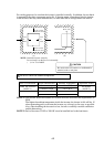
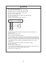
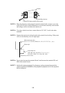
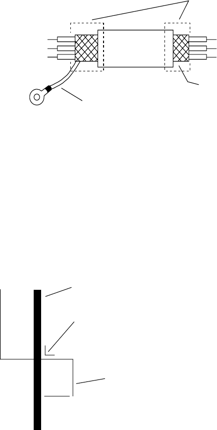
Insulate
No grounding necessary
Connect FG (frame ground) of the inverter.
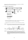
NOTE 3: When the frequency setting signal is turned on and off with a contact, use a relay
which will not cause contact malfunctions, even with the extremely weak currents
and voltages, such as crossbar twin contacts, etc.
NOTE 4: Use relays which do not have contact defects at 24 V DC, 3 mA for the other
terminals.
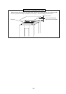
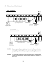
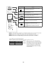
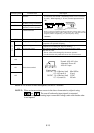
NOTE 5: Separate the main circuit wiring from the relay control circuit wiring. If they must
cross, be sure that they cross at a right angle.
➤
➤
➤
➤
➤
Main circuit power line
(R, S, T, U, V, W, PP, P, RB, N, L1, L2, L3, T1, T2, T3, +, -, etc.)
Right angle
Signal input line
(FM, CM1, PLC, P24, FW, 8, 7, 6, 5, 4, 3, 2, 1,
H, O, OI, L, CM2, 12, 11, AL0, AL1, AL2)
Separate by 10 cm or more.
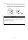
NOTE 6: Do not short between the terminals H and L and between the terminals P24 and
CM1 of the control circuit.
NOTE 7: Insulate the common terminal L for frequency analog command input and the
common terminal (COMMON) of the peripheral equipment such as the sequencer
before starting use.