


6-5
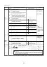
• The failure alarm signal is generated from the terminal AL0 and AL1 when a failure hap-
pens. At this time the contents of the failure are displayed on the digital operator.
• Whether the alarm terminal output is to be turned on or off during normal run can be
selected by the extension function .
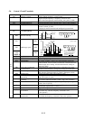
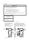
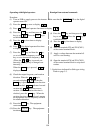
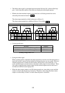
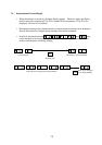
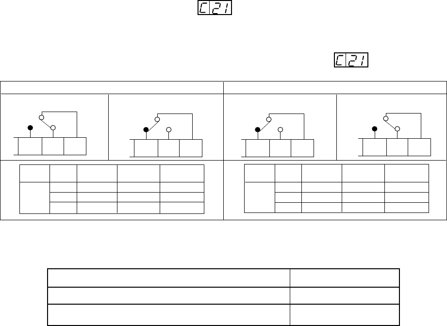
The alarm output terminals at initial setting are as follows (1).
The alarm output terminals are valiable as follows (2) by setting .
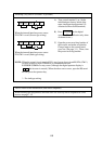
Operation
Status
(1) Contact b
(2) Contact a
During normal operation
At occurrence of an
alarm or power off
During normal operation
or at power off
At occurrence of an alarm
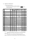
Contact Power Operation
Status
AL0-AL1 AL0-AL2
b
(initial
setting)
ON
ON
OFF
Normal
Closed Open
Abnormal Open Closed
ÑOpen Closed
Contact Power AL0-AL1 AL0-AL2
a
ON
ON
OFF
Normal Open Closed
Abnormal Closed Open
Open Closed
AL2 AL1 AL0
AL2 AL1 AL0 AL2 AL1 AL0
AL2 AL1 AL0
Ñ
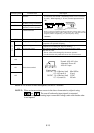
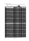
• Contact specification
250 VAC 2.5 A (Resistor load) 0.2 A (cos¿=0.4) 100 VAC 10 mA
30 VDC 3.0 A (Resistor load) 0.7 A (cos¿=0.4) 5 VDC 100 mA
MinimumMaximum
Working voltage: Max. 50 V
• Saving the alarm signal
When an alarm signal is outputted, the alarm signal data is stored even if the input power is
turned off and the contents can be checked by turning the power on once again. However,
when the input power is turned off, the inverter control power is also turned off. As a
result, when the power is turned on next, the alarm contact output is reset (deleted). There-
fore, when saving the alarm contact output, let the external sequence receive and save it
and then turn off the inverter input power.
• When the alarm contact output is set ON during normal run, a time delay occurs until the
contact is closed when the power is turned on. Therefore, when using the alarm contact
output, set a time delay of about 2 seconds when the power is turned on.