


5-14
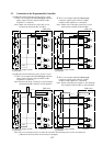
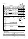
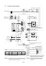
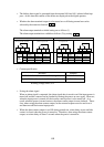
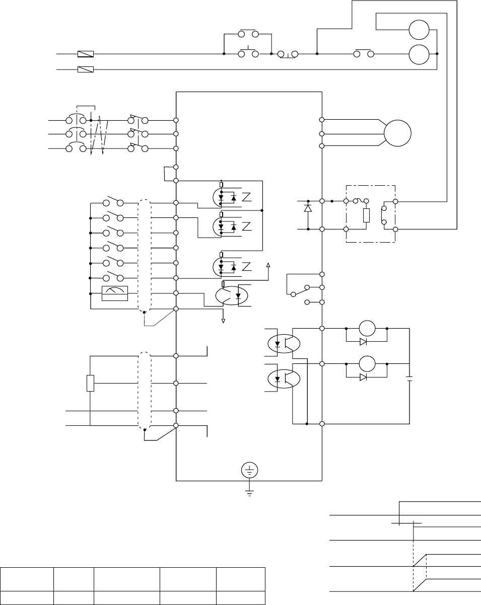
5.7 Terminal Connection Diagram
➤
➤
➤
➤
➤
➤
➤
➤
➤
➤
➤
➤
Power supply
Three phase
power supply
ELB
EF
Mg
Mg
BSS
BSS
AX
AX
Mg
Motor
R (L1)
S (L2)
T (L3)
P24
PLC
24 VDC
(T1) U
(T2) V
(T3) W
FW
8
7
1
.
.
.
.
.
FM
CM1
P24
(+) P
RB RB
P
AL1
AL1
AL0
AL1
AL2
11
12
10 VDC
RY
RY
24 VDC
Dynamic braking resistor
055, 075LF: RB1,RB2 or RB3
055, 075HF: RB2, two each in series.
Fault alarm signal
(Normal: AL0-AL1 ON)
H
O
OI
L
3
2
1
Frequency setter
500Ω to 2 kΩ
Current input
4 to 2\0 mA
G
(PE)
Grounding
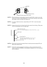
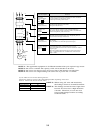
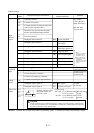
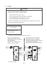
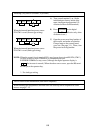
Follow the timing shown as below
upon power on.
Main circuit
power supply
Operation
command
Output
frequency
Number of
revolutions
of motor
(NOTE 4)
0.6 or more seconds
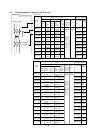
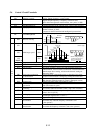
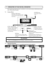
Terminal
name
Command CM1
FM
CM1 (P24)
FW, 8 to 1
L
H, O, OI
CM2
11, 12
*
NOTE 1: Common terminal for each terminal is different.
NOTE 2: The regenerative resistor has a temperature sensor.
When it works, turn off power supply to the inverter
o set the deceleration time longer.
*: P24 is for source type wiring.
NOTE 4: Do not input the operation command
simultaneously when the main circuit
is turned on.
NOTE 3: When the operation command is input first
and the main circuit power is turned ON,
and direct start results and a trip occurs.
CM2
Inverter