


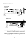
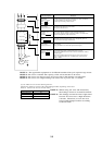
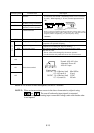
5-13
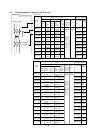
Terminal symbol Terminal name Description
H Frequency command power • Initialization of a voltage signal by an external command
terminal is between 0 and 10 VDC. (Switching from 0 to 5V is executed
by A48.) When inputting 4 - 20 mA, turn the input terminal at
ON.
O Frequency command
terminal (voltage command)
OI Frequency command
terminal (current command)
L Frequency command
common terminal
CM2 Common terminal 2 Common terminal for intelligent output terminal
FA1 Frequency arrival signal When each operator is used, and arrival signal can be
outputted at an optional frequency.
RUN Signal during run The transistor output is turned ON during running.
(Outputted even during DC injection braking)
OTQ Over-torque signal The transistor output is turned ON when the torque is more
than the set value.
The set value can be changed by the remote operator.
Use this function only under the sensor less vector control.
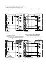
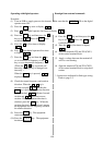
AL0
AL1 Fault alarm terminal
AL2
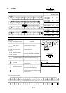
NOTE 1: To set four or more multispeeds, use the CF3 terminal.
NOTE 2: When an inconvernience occurs in the above characteristics, adjust it using
and . The sum of both analog input signals is outputted
When selecting one of analog input current and voltage, make sure that the other
is not inputted.
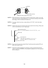
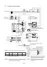
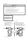
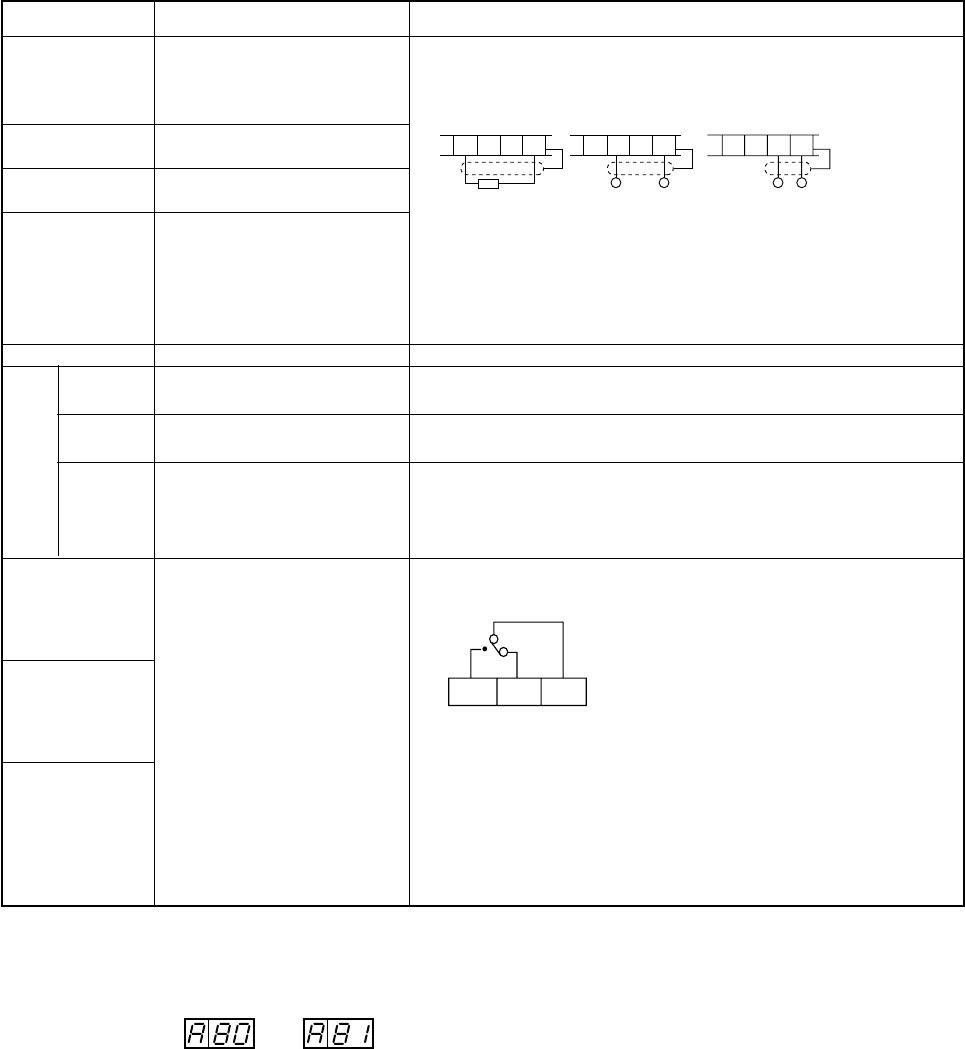
11 • 12
H O OI L
VRO
(500 Ω to 2 kΩ)
DC0 to 10 V
DC0 to 5V
Input impedance 30 kΩ
+- +-
HOOIL HOOIL
DC4 to 20 mV
Input impedance 250 kΩ
When a current is inputted from between OI and L and the value is 4 mA,
the output frequency may 0.6 Hz. If this occurs, set a value more than the
frequency which is outputted by [A 4] start frequency setting.
(NOTE 2)
AL2 AL1 AL0
Normal: AL0-AL1 close
Abnormal, Power off:
AL0-AL1 open
Contact rating
250 VAC
30 VDC
2.5 A (Resistor load)
0.2 A (Cosø=0.4)
3.0 A (Resistor load)
0.7 A (cosø=0.4)
Min 100Vac
10 mA
5 VDC
100 mA