


5-5
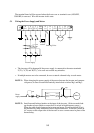
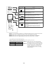
5.2 Wiring of Control Circuit Terminals
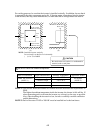
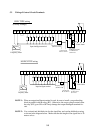
FM CM1PLCP24FW87654321HOOILCM21211AL2 AL1 AL0
Fre
q
uenc
y
meter
Input intelligent terminal
Frequency setting
(500 Ω to 2 kΩ)
Fault alarm
For output
Intelligent terminal
27 VDC 50 mA
50 mA max
Current input
DC 4 to 20 mA
RY
RY
SINK TYPE wiring
(Factory settings)
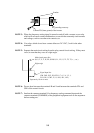
FM CM1PLCP24FW87654321HOOILCM21211AL2 AL1 AL0
Fre
q
uenc
y
meter
Input intelligent terminal
Frequency setting
(500 Ω to 2 kΩ)
Fault alarm
For output
Intelligent terminal
27 VDC 50 mA
50 mA max
Current input
DC 4 to 20 mA
RY
RY
SOURCE TYPE wiring
NOTE 1: When an output intelligent terminal is used, be sure to install a surge absorbing
diode in parallel with the relay (RY). Otherwise, the surge voltage created when
the relay (RY) goes ON or OFF may damage the output intelligent terminal cir-
cuit.
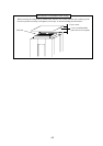
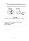
NOTE 2: Use a twisted and shielded wire for the signal line, and cut the shielded covering
as shown in the diagram below. Make sure that the length of the signal line is 20
meters or less.