


Chapter 2 • Installing the indoor equipment
16
1031484-0001 Revision 2
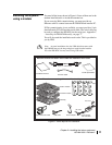
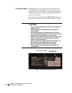
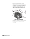
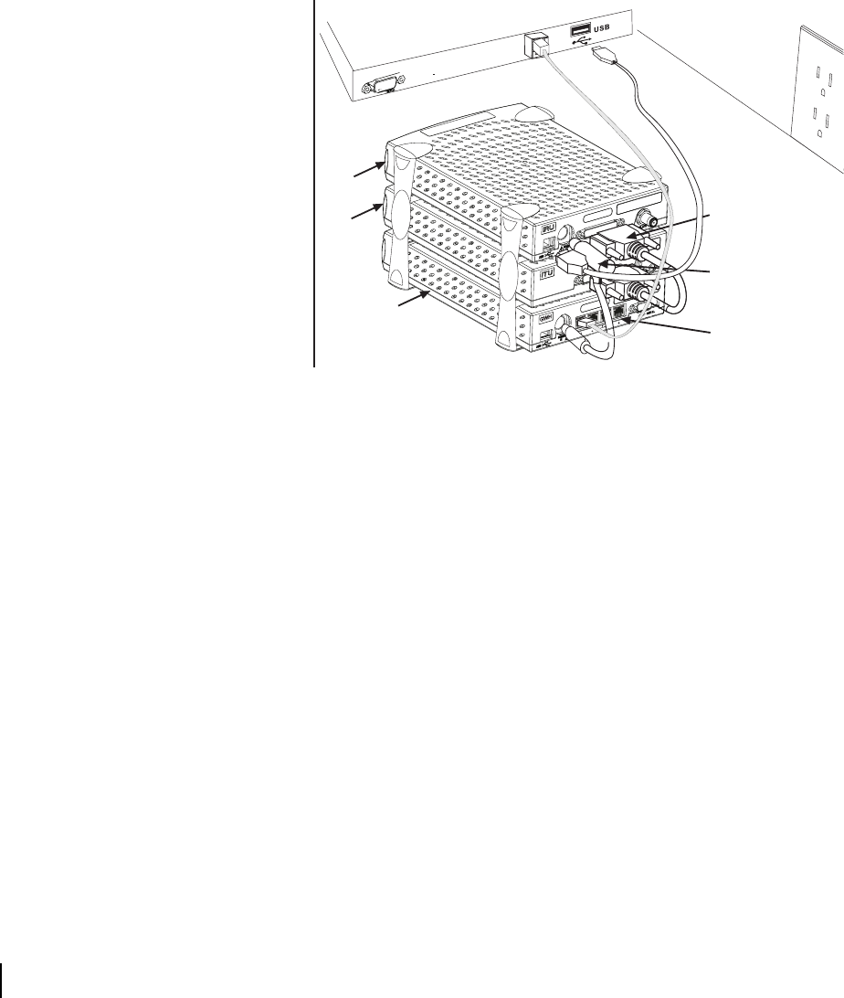
5. Connect the component interconnection cables. See
Figure 11. A USB cable connects the receive modem and the
installer PC; you may use a longer cable rather than the one
that is supplied if you wish. An Ethernet cable connects the
Gateway and the installer PC. A 25-pin connector cable
connects the transmit and receive modems. A power supply
adapter cable provides power to the Gateway and receive
modem. See Figure 11.
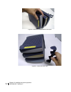
6. Attach the power supply cords to the power supply and to the
power adapter. Ensure that the power cord is tightly
connected to the power supply, receive modem, and Gateway.
See Figure 12.
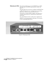
Figure 11: Attach interconnection cables
Transmit
modem
Ethernet port
Receive
modem
Gateway
Power supply
adapter
25-pin connector
cable
Four 10 Base - T/100
-
network ports
Ethernet cable
USB cable
Installer laptop PC