


Noise Measurement Methodology
•
•
•
•
•
•
•
•
•
•
•
•
•
•
•
•
•
•
•
•
•
•
•
•
•
•
•
•
•
•
•
•
•
•
•
•
•
•
•
•
•
•
•
•
•
•
•
•
•
•
•
•
•
•
•
•
•
•
JUNOSg 3.0 G10 CMTS Hardware Guide
84
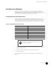
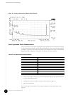
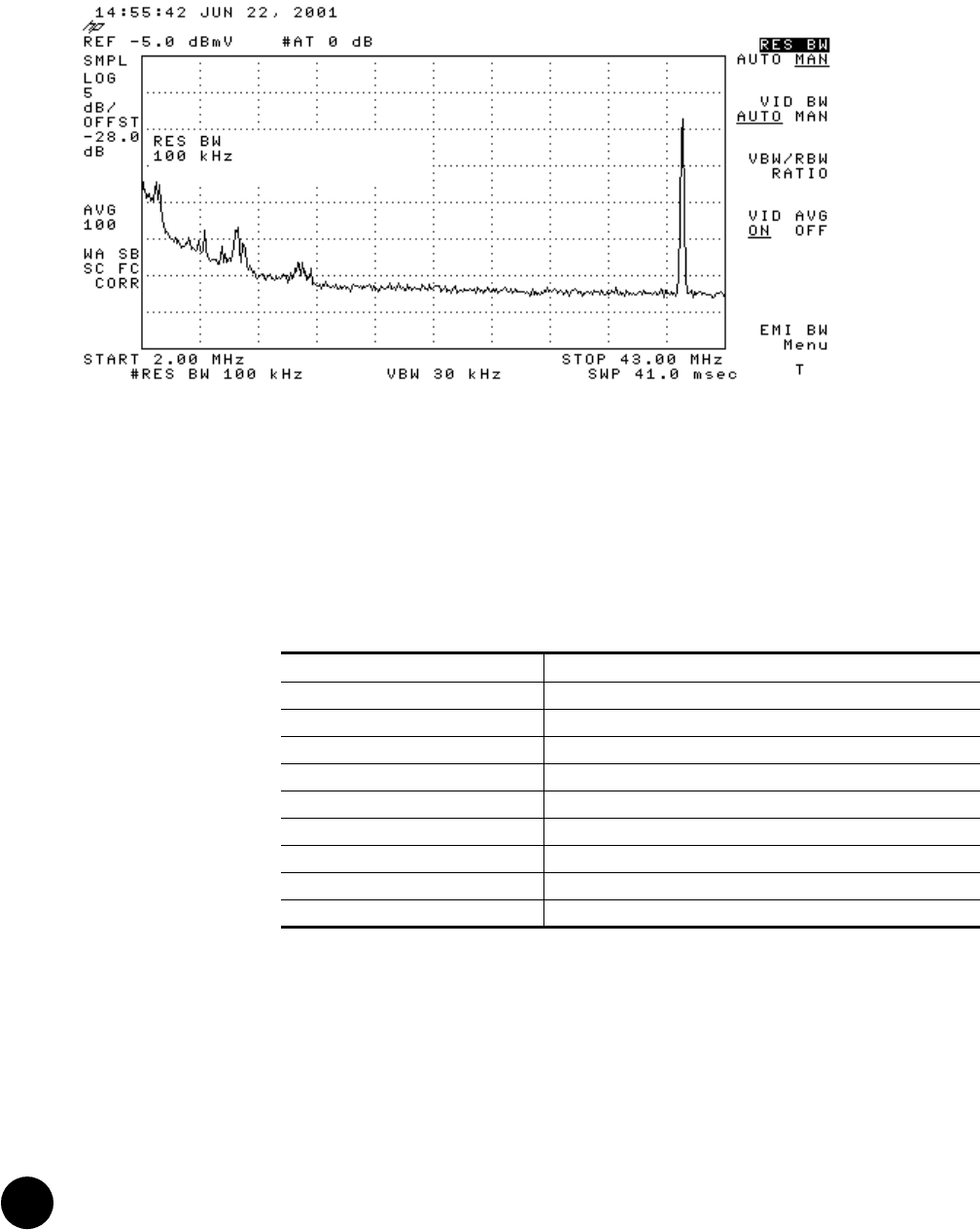
Figure 23: Average Upstream Noise Measurement Example
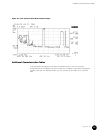
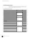
Peak Upstream Noise Measurement
This section defines a procedure for taking the peak upstream noise measurements required
as part of the RF plant and HFC environment characterization. We recommend that you take
a sample of 10 percent of the nodes terminated at the installation site. Table 34 provides the
appropriate setup configuration settings for the HP 8591C spectrum analyzer.
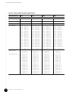
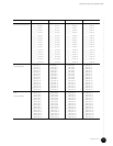
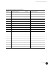
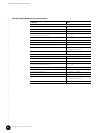
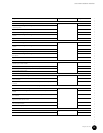
Table 34: Peak Noise Spectrum Analyzer Setup
1. Connect the spectrum analyzer to the selected upstream signal at the upstream splitter
or at the CMTS upstream port.
2. Configure the spectrum analyzer using the values defined in Table 34.
3. Start the measurement.
After completing the measurement, the analyzer display should resemble Figure 24 on
page 85.
Setting Value
Start frequency 2 MHz
Stop frequency 45 MHz
Resolution bandwidth 100 kHz
Video bandwidth 30 kHz
Scale 5 dB/div
Internal amplifier Off
Attenuator 0 dB
Reference level of headend 0 dBmV
Max Hold 1 minute