


Power On the G10 CMTS
•
•
•
•
•
•
•
•
•
•
•
•
•
•
•
•
•
•
•
•
•
•
•
•
•
•
•
•
•
•
•
•
•
•
•
•
•
•
•
•
•
•
•
•
•
•
•
•
•
•
•
•
•
•
•
•
•
•
JUNOSg 3.0 G10 CMTS Hardware Guide
126
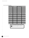
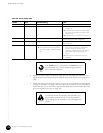
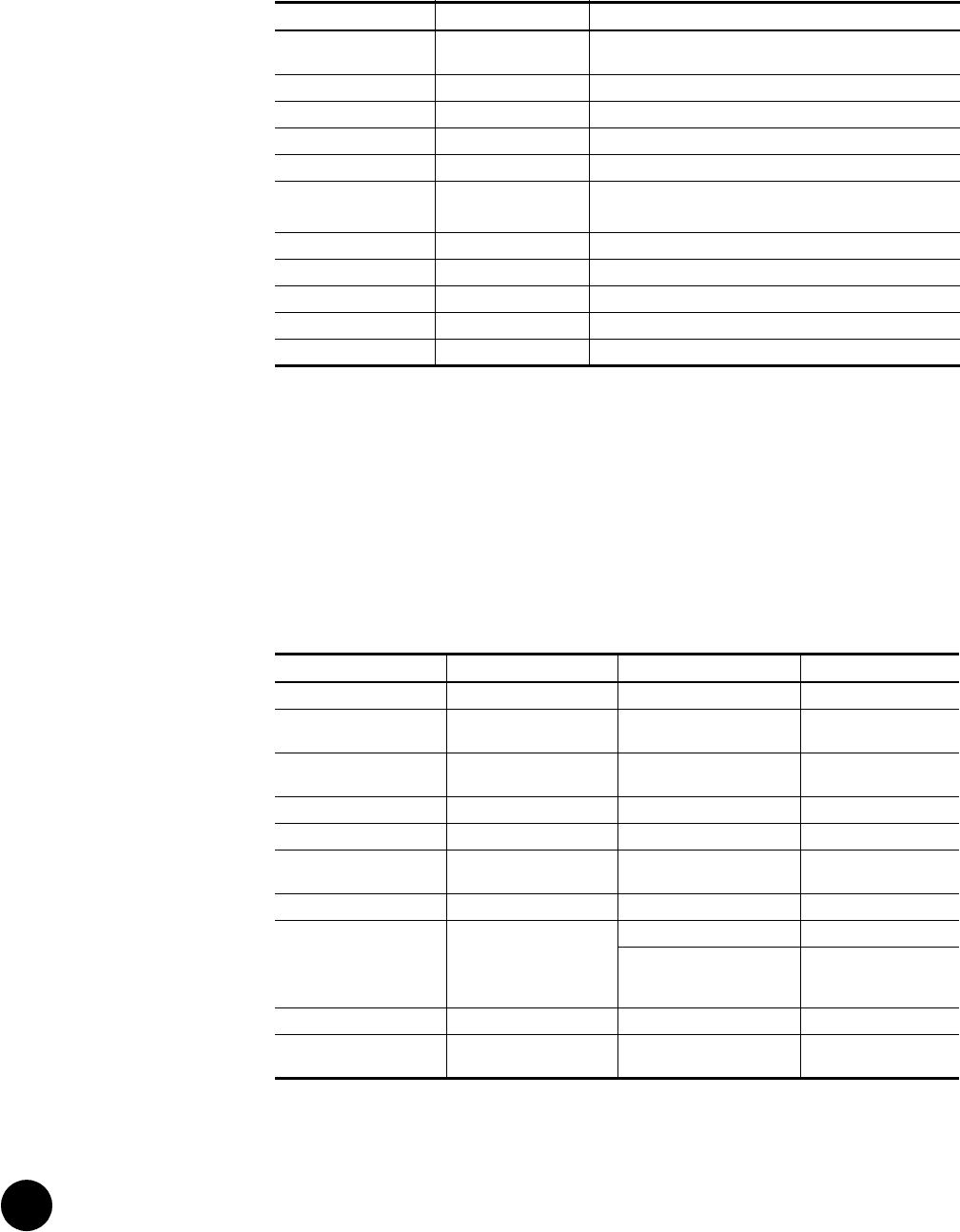
Table 42: Chassis Control Module LED Status
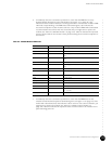
8. Immediately after the G10 CMTS is powered on, wait for the OK LED on the NIC Module
faceplate to illuminate green, which indicates the module initialization has been
successfully completed (see Figure 16 on page 43). Some LEDs will be in one state
during the initialization (OK LED not illuminated), then change to another state after the
initialization (OK LED illuminated green). Table 43 on page 126 indicates the expected
status of all LEDs on the module’s front panel. If the OK LED does not illuminate, the NIC
Module is considered faulty and you might have to replace it (see “Remove a NIC
Module” on page 170).
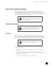
Table 43: NIC Module LED Status
9. You should check the four LEDs at the top of the NIC Access Module rear panel after
confirming the LEDs on its corresponding NIC Module are in the correct state as
LED Status Meaning
Minor Off No event of priority Warning, Notice, Information, or Critical
has occurred.
Major Off No event of priority Error has occurred.
Critical Off No event of priority Emergency, Alert, or Critical has occurred.
Run Green Module is active.
ACO Off Alarm Cutoff not activated.
∆1 ∆2 Green On—Active module.
Off—Stand-by module.
IDE Off IDE inactive.
Power Green Power is applied.
USR1 [TBD] [TBD]
USR2 [TBD] [TBD]
Hot Swap Off Not safe to remove module.
LED Pre-initialization Status Post-initialization Status Meaning
Pull Red Off Normal operation.
0 through 23 Off Off No link or activity on
interfaces.
GB0 and GB1 Off Off No link on Gigabit
interfaces.
CLK Green Off Undefined.
PWR Green Green Power is applied.
RTM Green Green Continuity established
with NAM.
OK Off Green Successful initialization.
EXT FLT Amber Off No external failure.
Amber One or more of the FE or
GE ports is enabled, but
unused.
INT FLT Amber Off No internal failure.
Hot Swap Off Off Not safe to remove
module.