


Power On the G10 CMTS
•
•
•
•
•
•
•
•
•
•
•
•
•
•
•
•
•
•
•
•
•
•
•
•
•
•
•
•
•
•
•
•
•
•
•
•
•
•
•
•
•
•
•
•
•
•
•
•
•
•
•
•
•
•
•
•
•
•
JUNOSg 3.0 G10 CMTS Hardware Guide
124
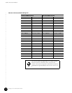
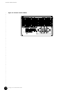
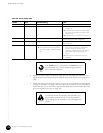
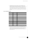
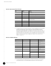
Table 40: Power Supply LEDs
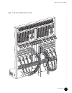
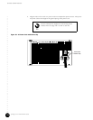
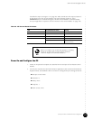
4. Replace the power supply faceplate by aligning its four ball studs with the four power
supply faceplate clips and pressing the faceplate towards the chassis until it snaps into
place.
5. Ensure that the fan tray LEDs (two in front, one in rear) are not illuminated (see Figure 4
on page 11 and Figure 7 on page 14 for the location of these LEDs). If any fan tray LED is
illuminated red, one or more fans in that tray has failed and you must replace the entire
tray (see “Replace a Fan Tray” on page 162).
POWER FAULT Potential Meaning Action
Green Not illuminated Normal operation None
Green Red Over-temperature ! Check that fan trays are operational (see step 5
on page 124).
! Ensure all empty module slots and power supply
bays contain air management modules, panels,
and filler panels.
! Ensure air intakes and exhaust are not blocked.
Green Red Over-current or over power limit condition Ensure that the correct number of power supplies are
installed to support the CMTS configuration.
Not illuminated Red Voltage input failure Ensure that the external power sources are operating
within specification.
Not illuminated Not illuminated ! Power supply not installed correctly.
! No input power and no DC output from
other power supplies to illuminate FAULT
LED.
! Power down the G10 CMTS and reinstall the
power supply as described on “Install Power
Supplies” on page 101. If power supply
redundancy is implemented, you can replace a
power supply without powering down the
system.
! Ensure that the external power sources are
switched on.
If the POWER LED is not illuminated, the FAULT LED can be
illuminated red only if the DC output voltage is present
from other power supplies.
To minimize the risk of damage to the G10 CMTS, you
should replace a failed fan tray as soon as possible to
ensure that proper air ventilation occurs throughout the
chassis.