


•
•
•
•
•
•
•
•
•
•
•
•
•
•
•
•
•
•
•
•
•
•
•
•
•
•
•
•
•
•
•
•
•
•
•
•
•
•
•
•
•
•
•
•
•
•
•
•
•
•
•
•
•
•
•
•
•
•
Prepare the Site
Characterization of Installation Site
77
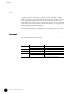
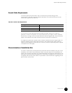
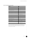
Table 28: Existing DOCSIS Service Characterization
Table 29 on page 78 and Table 30 on page 80 are provided to collect upstream and
downstream characterization information for a DOCSIS Module. If the CMTS configuration
includes more than one DOCSIS Module, additional tables are provided in “Additional
Characterization Tables” on page 85.
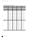
Parameter Value
1st DOCSIS Service
Upstream RF bandwidth allocated ____ MHz (max) ____ MHz (min)
Upstream modulation type ____ QPSK ____ 16QAM
Upstream input level expected at CMTS ____ dBmV
FEC enabled?
If yes, FEC level parameters (T and K)
____ yes ____ no
____T ____ K
Upstream measured C/N ____ dB
Downstream RF bandwidth allocated ____ MHz (max) ____ MHz (min)
Downstream modulation type ____ 64QAM ____256QAM
Downstream output signal level (relative to analog video) ____ dB
Downstream measured C/N ____ dB (DOSCIS carrier)
____ dB (Analog video carrier)
Downstream interleave depth setting ___ (# of taps) ____(increments)
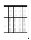
2nd DOCSIS Service
Upstream RF bandwidth allocated ____ MHz (max) ____ MHz (min)
Upstream modulation type ____ QPSK ____ 16QAM
Upstream input level expected at CMTS ____ dBmV
FEC enabled?
If yes, FEC level parameters (T and K)
____ yes ____ no
____ T ____ K
Upstream measured C/N ____ dB
Downstream RF bandwidth allocated ____ MHz (max) ____ MHz (min)
Downstream modulation type ____ 64QAM ____256QAM
Downstream output signal level (relative to analog video) ____ dB
Downstream measured C/N ____ dB (DOCSIS carrier)
____ dB (Analog video carrier)
Downstream interleave depth setting ___ (# of taps) ____(increments)