


Chassis Rear Modules
•
•
•
•
•
•
•
•
•
•
•
•
•
•
•
•
•
•
•
•
•
•
•
•
•
•
•
•
•
•
•
•
•
•
•
•
•
•
•
•
•
•
•
•
•
•
•
•
•
•
•
•
•
•
•
•
•
•
JUNOSg 3.0 G10 CMTS Hardware Guide
48
Chassis Rear Modules
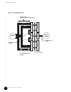
The rear modules, in general, are designed to locate the chassis cable connections on the
back of the chassis rather than the front. The rear modules primarily distribute signals
between the functional modules in front and the cabling in the rear.
This section discusses the following chassis rear modules:
! NIC Access Module on page 48
! HFC Connector Module on page 50
! Switched I/O Module on page 53
! Hard Disk Module on page 55
NIC Access Module
The NIC Access Module contains a 6 U (267 mm) x 80 mm card with a 4 HP (20 mm),
single-wide rear panel. The module installs from the rear of the chassis and is hot-swappable.
There must be one NIC Access Module opposite each NIC Module.
The NIC Access Module passes the network traffic through the midplane as Fast Ethernet
frames to and from the NIC Module. The module has two RJ-21 connectors. A NIC Access
Module cable plugs into each connector and fans out to 12 individual lines with RJ-45
connectors. Eight of the RJ-45 connectors from the NIC Access Module cable plugged into
connector 1 mate with the HFC Connector Modules or SIMs within the same chassis domain.
The NIC Access Module cable plugged into connector 2 provides four RJ-45 connectors that
are the Fast Ethernet interfaces. See “HFC Connector Module” on page 50 and “Switched I/O
Module” on page 53 for more discussion and an illustration of the data flow path.
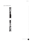
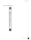
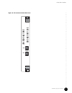
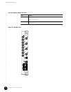
Table 22 describes the functions of the NIC Access Module LEDs. Figure 17 on page 49 shows
the NIC Access Module rear panel.
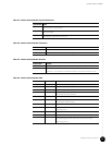
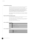
Table 22: NIC Access Module LEDs
LED Color Function
POWER Green ON—Power is applied to the module.
OPERATIONAL Green ON—Initialization successfully completed.
INT FAULT Green ON—Failure detected in the module.
EXT FAULT Amber ON—One or more of the Fast Ethernet or Gigabit
Ethernet ports is enabled, but unused.