


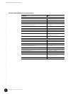
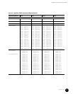
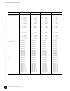
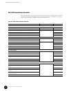
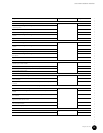
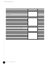
G10 CMTS Installation Checklist
•
•
•
•
•
•
•
•
•
•
•
•
•
•
•
•
•
•
•
•
•
•
•
•
•
•
•
•
•
•
•
•
•
•
•
•
•
•
•
•
•
•
•
•
•
•
•
•
•
•
•
•
•
•
•
•
•
•
JUNOSg 3.0 G10 CMTS Hardware Guide
92
Connect to Power Sources
Ensure that each power distribution rocker switch is OFF (AC only) page 119
Plug each power cord into the power receptacles (AC) or terminal blocks (DC)
Close the retainer clips around the power cords (AC) or secure the DC ring lugs to the
terminal blocks (DC)
Plug the other ends of the power cords to their respective, independent power sources
Power On the G10 CMTS
Ensure that the power sources are on page 123
Turn on the power switches on the power transition modules (AC only)
Check all power supply LEDs (power supply faceplate must be removed, then replaced)
Check front and rear fan tray LEDs
Check all DOCSIS Module LEDs
Check all Chassis Control Module LEDs
Check all NIC Module LEDs
Power On and Configure the PC
Power on the PC, launch the asynchronous terminal emulation application, and
establish a direct serial connection with the Chassis Control Module
page 127
Check for correct boot banner and system prompt on PC
Log into the G10 CMTS
Perform Initial Software Configuration
Configure the name of the CMTS page 128
Configure the CMTS’s domain name
Configure the IP address of the Fast Ethernet management port
Configure the IP address of a backup router
Configure the IP address of a DNS server
Set the root authentication password
Step Page Number Completion Status