


G10 CMTS Installation Checklist
•
•
•
•
•
•
•
•
•
•
•
•
•
•
•
•
•
•
•
•
•
•
•
•
•
•
•
•
•
•
•
•
•
•
•
•
•
•
•
•
•
•
•
•
•
•
•
•
•
•
•
•
•
•
•
•
•
•
JUNOSg 3.0 G10 CMTS Hardware Guide
90
G10 CMTS Installation Checklist
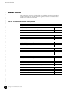
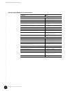
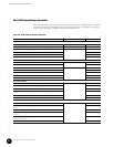
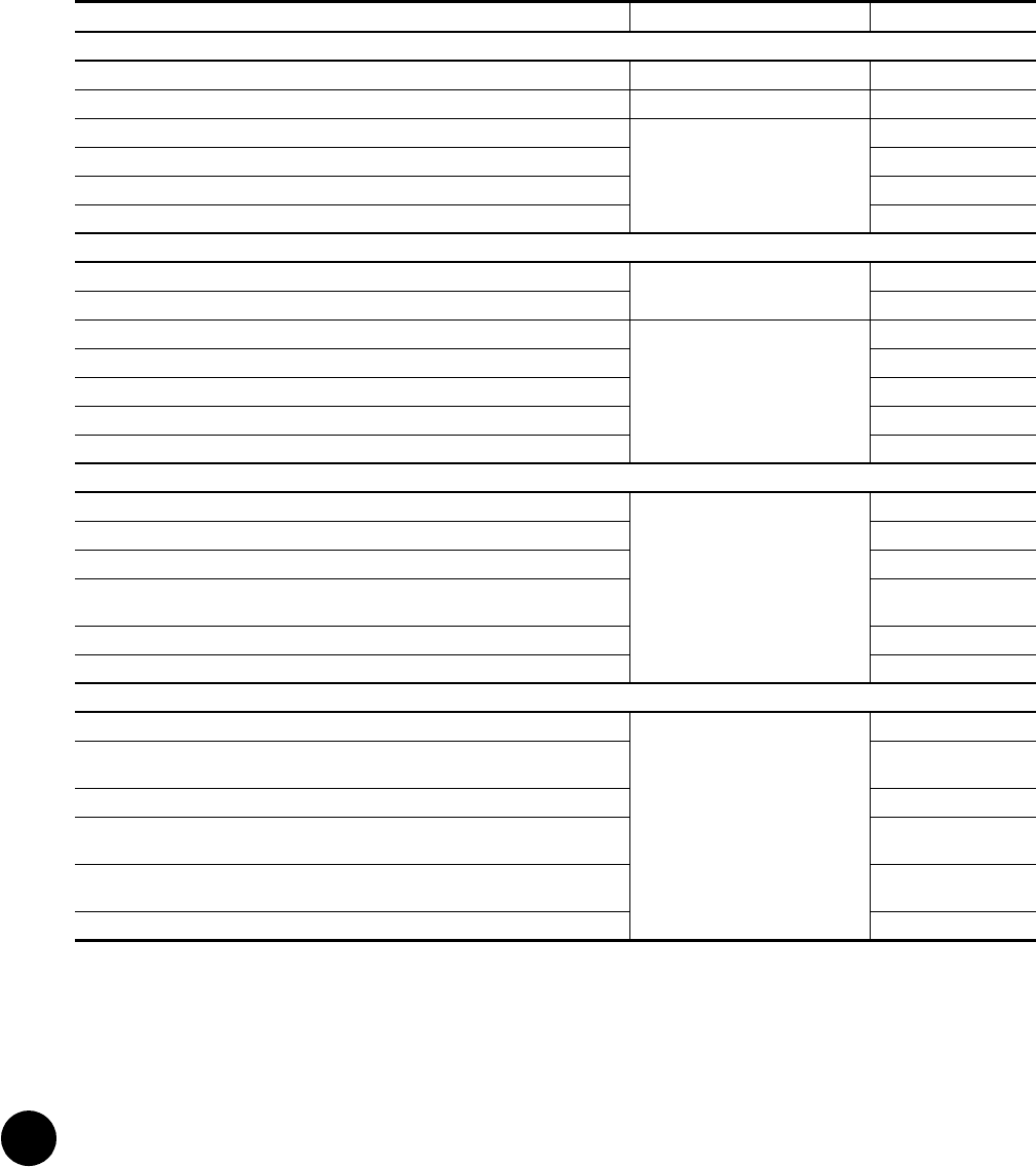
Table 38 summarizes all the steps outlined in this document that are required to successfully
install the G10 CMTS in the headend. We recommend that copies of this table be made and
used to keep track of the installation status of each G10 CMTS.
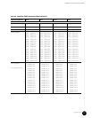
Table 38: G10 CMTS Installation Checklist
Step Page Number Completion Status
Preparation for Installation
Complete all checklists in “Prepare the Site” page 67
Completely review the G10 CMTS Hardware Guide, including the safety precautions —
Verify the contents of the shipping cartons page 89
Verify the number of pre-installed modules and power supplies in the chassis is correct
Verify the contents of all accessory kits
Install the power supply faceplate and the air intake faceplate
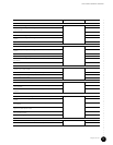
Ground and Rack Mount the Chassis
Crimp the supplied two-ring lug connector to the earth ground strap page 94
Attach the earth ground strap to the chassis
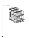
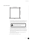
Ensure proper ventilation clearance surrounding the G10 CMTS page 94
Install an equipment shelf in the rack
If applicable, install the rack mounting brackets
Slide the chassis onto the shelf and mount it to the rack
Attach the earth ground strap to earth ground
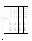
Install Power Supplies
Remove the power supply faceplate page 101
Determine the bay in which to install the power supply
Remove the power supply filler panel
Release the ejector, align to the card guides, insert the power supply, and close the
ejector
Tighten the self-contained screws
Replace the power supply faceplate
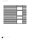
Install a DOCSIS Module and an HFC Connector Module or SIM
Remove the air management module where the DOCSIS Module will be inserted page 103
Release the ejectors, align to the card guides, insert the DOCSIS Module, and close the
ejectors
Tighten the self-contained screws
Remove the air management panel where the HFC Connector Module or SIM will be
inserted
Release the ejectors, align to the card guides, insert the HFC Connector Module or SIM,
and close the ejectors
Tighten the self-contained screws