


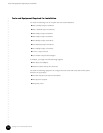
Characterization of Installation Site
•
•
•
•
•
•
•
•
•
•
•
•
•
•
•
•
•
•
•
•
•
•
•
•
•
•
•
•
•
•
•
•
•
•
•
•
•
•
•
•
•
•
•
•
•
•
•
•
•
•
•
•
•
•
•
•
•
•
JUNOSg 3.0 G10 CMTS Hardware Guide
76
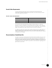
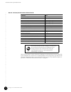
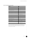
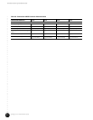
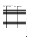
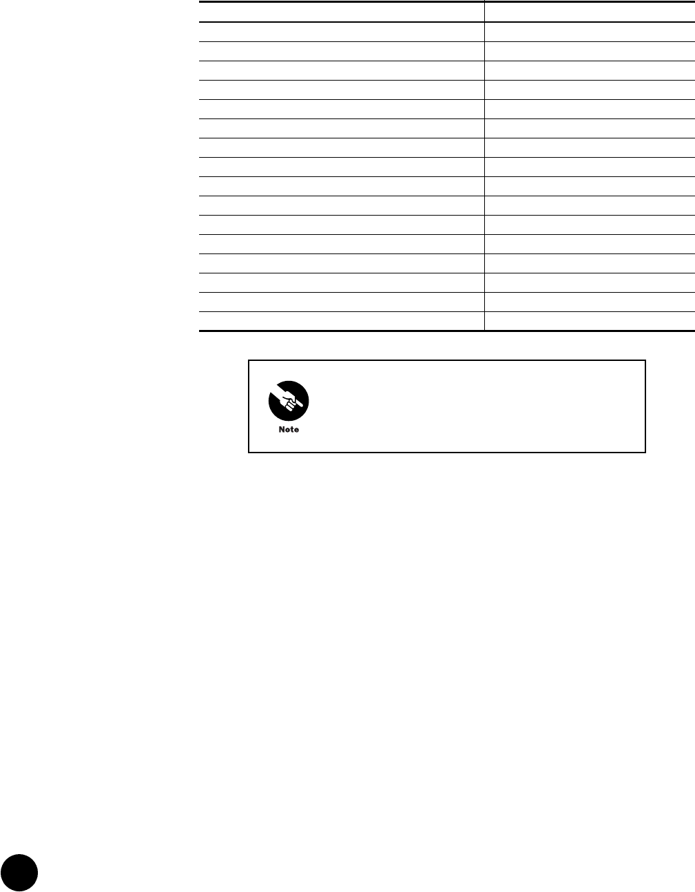
Table 27: RF Plant/HFC Environment Characterization
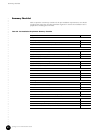
Table 28 is provided to collect information regarding the existing DOCSIS services supported
by the installation site. If there are no existing DOCSIS services supported, skip Table 28 and
proceed to subsequent tables. If more than two DOCSIS services exist, additional tables are
provided in “Additional Characterization Tables” on page 85.
Parameter Value
Plant architecture type ____ HFC ____ All Coax
Number of optical links within HFC
Distance between optical links within HFC ____ max ____ average
Amplifier cascade depth from node ____ max ____ average
Homes passed per node ____ max ____ average
Total homes passed by installation site
Node combining ratio per port ___:1 upstream ___:1 downstream
Average upstream noise measurement (see note below) ____ dB
Peak upstream noise measurement (see note below) ____ dB
Passive loss from upstream receiver to CMTS ____ dB
Maximum tap value used ____ dB
Maximum tap output level at highest frequency ____ dBmV
Maximum drop loss allowed from tap to home ____ dB
Method used for return path alignment
DOCSIS services offered? If yes, complete Table 28 on page 77. ____ yes ____ no
Upstream frequency spectrum utilization (complete Table 31 on page 81)
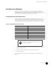
We recommend that you take a sample of 10 percent of
the total nodes terminated at the installation site for
average and peak noise measurements using the
methodology described in “Noise Measurement
Methodology” on page 83.