


Upstream RF Measurement
•
•
•
•
•
•
•
•
•
•
•
•
•
•
•
•
•
•
•
•
•
•
•
•
•
•
•
•
•
•
•
•
•
•
•
•
•
•
•
•
•
•
•
•
•
•
•
•
•
•
•
•
•
•
•
•
•
•
JUNOSg 3.0 G10 CMTS Hardware Guide
138
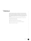
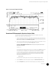
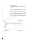
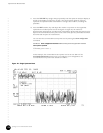
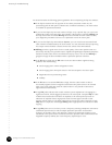
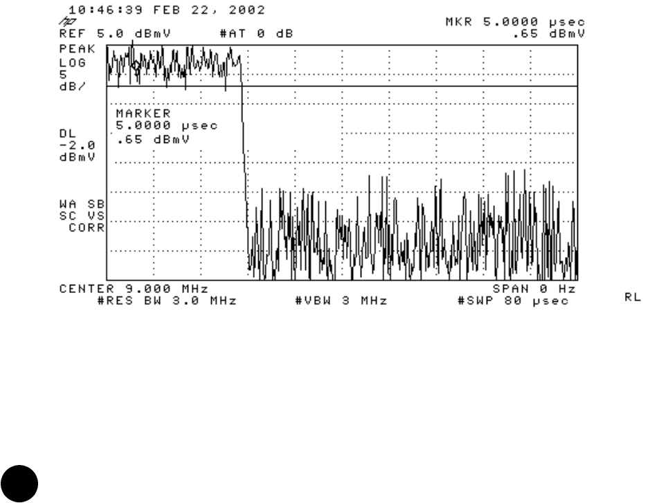
11. Press the SGL SWP key (single sweep) repeatedly until the spectrum analyzer display is
similar to the display in Figure 42 on page 138. The first three graticule columns
represent the upstream burst transmission of a single cable modem, including the
preamble.
12. Press the MKR (marker) key and adjust the marker to a position on the signal that
represents the median power level of the signal. In Figure 42, the marker is
approximately positioned at a median level of 0.65 dBmV. Ensure that this power level is
equal to the commanded receive power level at the CMTS, plus any attenuation between
the CMTS and the point of measurement.
You can view the commanded receive power level by issuing the show configuration
command:
user@host> show configuration interfaces cu-virtual-slot/docsis-slot/upstream-interface
cable-options upstream
...
commanded-power-level 0;
...
In this example, the commanded receive power level is set to 0 dBmV. If the
commanded-power-level statement is not included in your configuration, the
commanded receive power level defaults to 0 dBmV.
Figure 42: Single Upstream Burst