


•
•
•
•
•
•
•
•
•
•
•
•
•
•
•
•
•
•
•
•
•
•
•
•
•
•
•
•
•
•
•
•
•
•
•
•
•
•
•
•
•
•
•
•
•
•
•
•
•
•
•
•
•
•
•
•
•
•
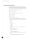
RF Measurements
Downstream RF Measurement in Spectrum Analyzer Mode
135
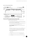
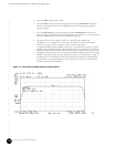
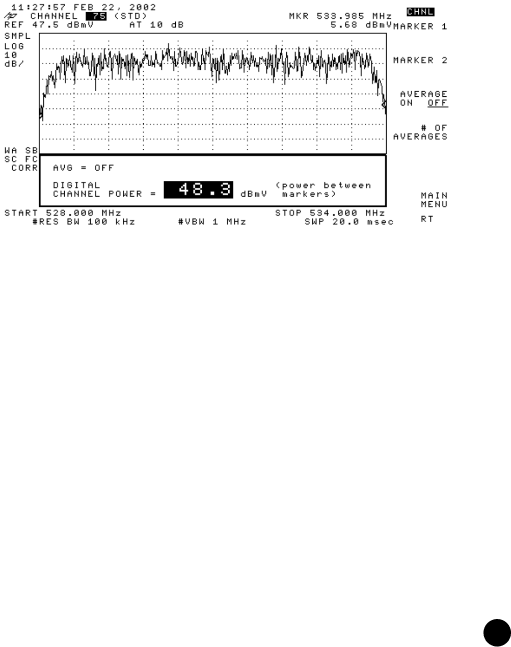
Figure 40: Downstream RF Signal (CATV Mode)
Downstream RF Measurement in Spectrum Analyzer Mode
To measure the downstream signal power using the spectrum analyzer mode on the
HP8591C CATV analyzer, follow this procedure:
1. Connect the spectrum analyzer to a cable within the plant that carries the downstream
signal you are measuring. The signal originates from one of the downstream ports of the
HFC Connector Module or the SIM (DS0 through DS3).
2. View (or set) the output RF power level of the specific interface to be measured. You can
view the output power by issuing the show configuration command:
user@host> show configuration interfaces cd-virtual-slot/docsis-slot/downstream-interface
cable-options downstream
...
rf-power 61;
...
In this example, the output RF power level is set to 61 dBmV. If the rf-power statement is
not included in your configuration, the output RF power level defaults to 61 dBmV.
To set the output RF power level for a downstream interface, include the rf-power
statement at the [edit interfaces cd-virtual-slot/docsis-slot/downstream-interface
cable-options downstream] hierarchy level:
rf-power rf-power;
The downstream interface power level can be from 50 dBmV through 61 dBmV.
3. Press the MODE key and set the spectrum analyzer to SPECTRUM ANALYZER mode.
4. Press the FREQUENCY key and enter the desired frequency (for example, 531 MHz).