


Radio Frequency (RF) Specifications
•
•
•
•
•
•
•
•
•
•
•
•
•
•
•
•
•
•
•
•
•
•
•
•
•
•
•
•
•
•
•
•
•
•
•
•
•
•
•
•
•
•
•
•
•
•
•
•
•
•
•
•
•
•
•
•
•
•
JUNOSg 3.0 G10 CMTS Hardware Guide
176
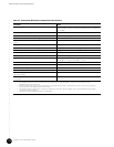
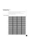
Table 47: Downstream RF Channel Transmission Characteristics
Parameter Value
Frequency range Cable system normal downstream operating range is from 50 MHz to as
high as 860 MHz. However, the values in this table apply only at frequencies
>= 88 MHz.
RF channel spacing (design bandwidth) 6 MHz
Transit delay from headend to most distant customer <= 0.800 msec (typically much less)
Carrier-to-noise ratio in a 6-MHz band (analog video level) Not less than 35 dB
4
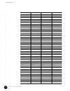
Carrier-to-interference ratio for total power (discrete and broadband ingress
signals)
Not less than 35 dB within the design bandwidth
Composite triple beat distortion for analog modulated carriers Not greater than -50 dBc within the design bandwidth
Composite second order distortion for analog odulated carriers Not greater than -50 dBc within the design bandwidth
Cross-modulation level Not greater than -40 dBc within the design bandwidth
Amplitude ripple 0.5 dB within the design bandwidth
Group delay ripple in the spectrum occupied by the CMTS 75 ns within the design bandwidth
Micro-reflections bound for dominant echo -10 dBc @ <= 0.5 m sec, -15 dBc @ <= 1.0 m sec
-20 dBc @ <= 1.5 m sec, -30 dBc @ > 1.5 m sec
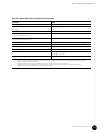
Carrier hum modulation Not greater than -26 dBc (5%)
Burst noise Not longer than 25 m sec at a 10 Hz average rate
Seasonal and diurnal signal level variation 8 dB
Signal level slope, 50-750 MHz 16 dB
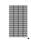
Maximum analog video carrier level at the CM input, inclusive of above
signal level variation
17 dBmV
Lowest analog video carrier level at the CM input, inclusive of above signal
level variation
-5 dBmV
1. Transmission is from the headend combiner to the CM input at the customer location.
2. For measurements above the normal downstream operating frequency band (except hum), impairments are referenced to the
highest-frequency NTSC carrier level.
3. For hum measurements above the normal downstream operating frequency band, a continuous-wave carrier is sent at the test frequency
at the same level as the highest-frequency NTSC carrier.
4. This presumes that the digital carrier is operated at analog peak carrier level. When the digital carrier is operated below the analog peak
carrier level, this C/N may be less.
5. Measurement methods defined in [NCTA] or [CableLabs2].