


•
•
•
•
•
•
•
•
•
•
•
•
•
•
•
•
•
•
•
•
•
•
•
•
•
•
•
•
•
•
•
•
•
•
•
•
•
•
•
•
•
•
•
•
•
•
•
•
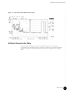
Install the CMTS
93
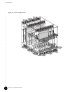
Chapter 5
Install the CMTS
This chapter describes the complete installation procedure for the G10 CMTS. It is assumed
that you have followed all safety precautions and procedures described in “Prepare the Site”
on page 67 prior to performing the procedures presented in this chapter. We recommend
that the entire installation process in this chapter be read prior to performing the actual
G10 CMTS installation.
This chapter discusses the following topics:
! Ground the Chassis on page 94
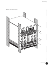
! Rack Mounting on page 94
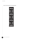
! Install Power Supplies on page 101
! Install a DOCSIS Module on page 103
! Install an HFC Connector Module or SIM on page 105
! Install a Chassis Control Module on page 108
! Install a Hard Disk Module on page 108
! Install a NIC Module on page 108
! Install a NIC Access Module on page 108
! Cable an HFC Connector Module or SIM on page 109
! Cable a Chassis Control Module on page 113
! Cable a NIC Module on page 113
! Cable a NIC Access Module on page 115
! Attach a PC to the Chassis Control Module on page 119
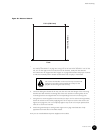
Before installing a power supply or any module into the
G10 CMTS, attach one end of an ESD ground strap to your
wrist and attach the other end to the ESD strap jack on the
front of the chassis (see Figure 5 on page 12).