


•
•
•
•
•
•
•
•
•
•
•
•
•
•
•
•
•
•
•
•
•
•
•
•
•
•
•
•
•
•
•
•
•
•
•
•
•
•
•
•
•
•
•
•
•
•
•
•
•
•
•
•
•
•
•
•
•
•
Install the CMTS
Cable a Chassis Control Module
113
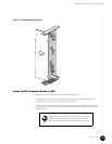
Cable a Chassis Control Module
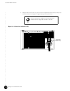
The Chassis Control Module contains a Fast Ethernet RJ-45 port labeled Eth0 on its front
panel (see Figure 15 on page 39). This port is used for the management interface to the
CMTS.
To connect to the Chassis Control Module management port, follow this procedure:
1. Carefully thread the Ethernet cable into the cable channel from the rear of the chassis
(see Figure 6 on page 13) until it extends through the opening of the power supply
faceplate.
2. Plug the RJ-45 connector of the Ethernet cable into the RJ-45 port of the Chassis Control
Module labeled Eth0.
3. Attach the other end of the Ethernet cable to its network equipment in the headend.
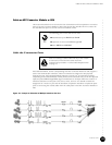
Cable a NIC Module
The NIC Module contains two full-duplex, Gigabit Ethernet GBIC transceiver ports on its front
panel. See “NIC Module” on page 42 for the specifications of the various types of GBIC
interfaces provided.
To connect the network cables to the Gigabit Ethernet ports, follow this procedure (see
Figure 16 on page 43 for port labeling):
1. Carefully thread each of the two cables into the cable channel from the rear of the
chassis (see Figure 6 on page 13) until they extend through the opening of the power
supply faceplate.
2. Connect the transmit/receive pair of each of these cables to the GBIC ports labeled 0
and 1 on the NIC Module.
3. Attach the other end of each cable to its network equipment in the headend.
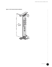
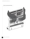
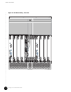
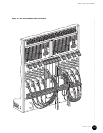
Figure 36 on page 114 provides the front view of the chassis with the network cables installed
into a NIC Module.
If using optical cables, avoid bending the cables too
sharply when threading them through the cable channel.