


•
•
•
•
•
•
•
•
•
•
•
•
•
•
•
•
•
•
•
•
•
•
•
•
•
•
•
•
•
•
•
•
•
•
•
•
•
•
•
•
•
•
•
•
•
•
•
•
•
•
•
•
•
•
•
•
•
•
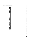
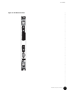
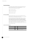
Hardware Component Overview
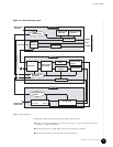
Chassis Control Module
41
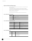
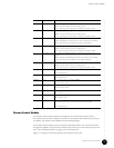
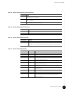
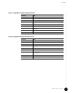
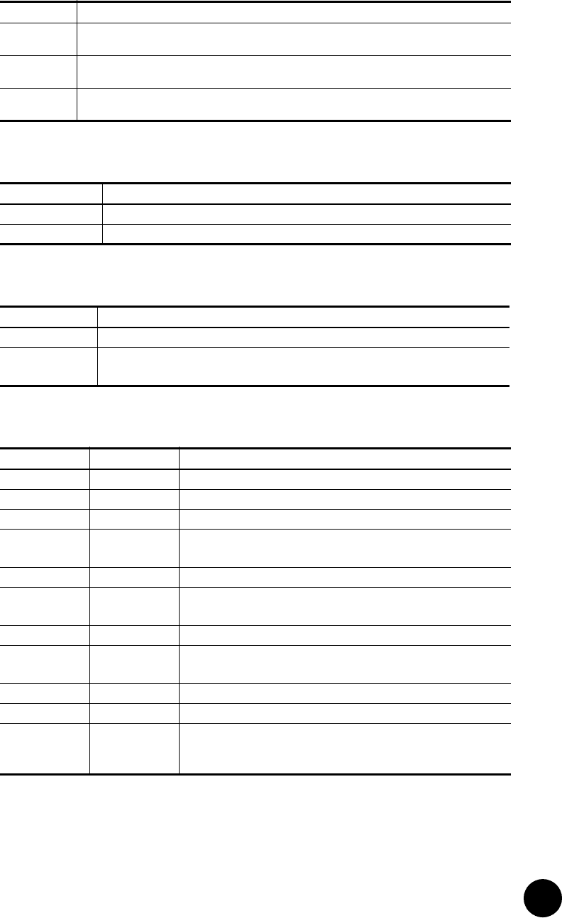
Table 11: Chassis Control Module Physical Dimensions
Table 12: Chassis Control Module Connectors
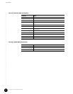
Table 13: Chassis Control Module Switches
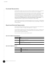
Table 14: Chassis Control Module LEDs
Specification Value
Height 233 mm (9.2 in.) module
262 mm (10.3 in., 6 U) front panel
Width 20 mm (0.8 in.)
(front panel width)
Depth 340 mm (13.4 in.)
(excluding front panel and cPCI connectors)
Connector Label Function
COM RS-232 DB-9 connector for serial interface.
Eth0 Fast Ethernet RJ-45 connector for CMTS management.
Switch Label Function
Cut-off Disables audible alarm signals. Causes ACO LED to illuminate.
Reset Depress for < 2 sec—Soft reset. Module is reinitialized.
Depress for > 2 sec—Hard reset. All module components, except Host Controller, are reset.
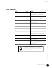
LED Label Color Function
Minor Green On—Event of priority Warning, Notice, Information, or Critical has occurred.
Major Amber On—Event of priority Error has occurred.
Crit Red On—Event of priority Emergency, Alert, or Critical has occurred.
Run Green / Red Green—Module is active.
Red—Module has been deactivated.
ACO Green On—Alarm Cutoff is activated.
∆1 ∆2 Green On—Active module.
Off—Stand-by module (not used).
IDE Green Not used.
Power Green / Red Green—Power on.
Red—Fault present.
USR1 Bi-color Not used.
USR2 Bi-color Not used.
Hot Swap Blue ON—Module is ready to be removed. Illuminates after the ejector release is
pressed. During hot insertion, LED is ON until ejectors are locked.
OFF during power up.