


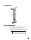
Install an HFC Connector Module or SIM
•
•
•
•
•
•
•
•
•
•
•
•
•
•
•
•
•
•
•
•
•
•
•
•
•
•
•
•
•
•
•
•
•
•
•
•
•
•
•
•
•
•
•
•
•
•
•
•
•
•
•
•
•
•
•
•
•
•
JUNOSg 3.0 G10 CMTS Hardware Guide
106
3. If the upper or lower ejector of the module is locked in the horizontal position, press
upward or downward on the ejector release while simultaneously pulling the ejector
away from the module faceplate. Each ejector should rest at approximately 45° away
from its locked position.
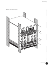
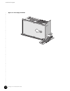
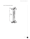
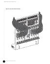
4. Each card cage slot in the rear of the chassis has an upper and lower card guide. Align
the printed circuit board of the module with the card guides and slowly slide the module
into the slot until it comes to a stop (action #1 in Figure 33 on page 107). The inside tabs
(tabs closest to midplane) of the upper and lower ejectors should be resting directly
under and over the module ejector rail.
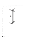
5. Simultaneously push the ejectors toward the module faceplate until they are horizontal
and each ejector clicks into position. The module faceplate should be flush with the
faceplate of any other adjacent module.
6. Tighten the two retainer screws by applying 3 in-lb of torque to each screw.
When you install a rear chassis module, apply more
pressure to the upper ejector than to the lower ejector. This
ensures the module connectors on the top of the card edge
are properly aligned with the midplane connectors. The
bottom edge has no connectors, so you do not need to
press the rear ejector as firmly.