


•
•
•
•
•
•
•
•
•
•
•
•
•
•
•
•
•
•
•
•
•
•
•
•
•
•
•
•
•
•
•
•
•
•
•
•
•
•
•
•
•
•
•
•
•
•
•
•
•
•
•
•
•
•
•
•
•
•
Prepare the Site
Coaxial Cable Requirements
75
Coaxial Cable Requirements
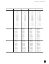
To achieve optimal RF performance and to minimize the potential damage of the
F-connectors on the HFC Connector Modules and SIMs, we recommend that you use the
coaxial cable types listed in Table 26.
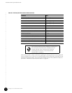
Table 26: Coaxial Cable Requirements
You can use any of the cable types listed in Table 26 initially. However, if a cable in a
particular F-connector is replaced, we recommend that the you replace it with a cable that
has the same, or larger, center conductor diameter than the original cable. This ensures that
proper contact between the cable conductor and an F-connector is maintained.
If a replacement cable has a smaller center conductor diameter than the original cable—for
example, replacing an RG-6 cable with an RG-59U—the smaller RG-59U cable conductor
might not make adequate contact with an F-connector, which can potentially lead to a partial
or complete loss of the signal.
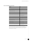
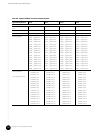
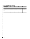
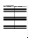
Characterization of Installation Site
You need to characterize several parameters associated with the installation site prior to the
installation of the CMTS. These parameters relate to specific aspects of the installation site
system, HFC network connections, and CMTS downstream and upstream transmissions. The
information collected allows field engineers to verify that the installation site environment is
compatible with the G10 CMTS. Table 27 is provided to collect information regarding the RF
plant and HFC environment.
Cable Type Diameter of Center Conductor
RG-59/U 0.57 mm (0.022 in)
RG-59 0.86 mm (0.034 in)
RG-6 1.05 mm (0.041 in)