


Chassis
•
•
•
•
•
•
•
•
•
•
•
•
•
•
•
•
•
•
•
•
•
•
•
•
•
•
•
•
•
•
•
•
•
•
•
•
•
•
•
•
•
•
•
•
•
•
•
•
•
•
•
•
•
•
•
•
•
•
JUNOSg 3.0 G10 CMTS Hardware Guide
20
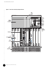
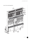
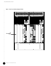
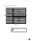
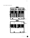
The major components of the G10 CMTS chassis are listed below and discussed in detail in
the following chapters.
! DOCSIS Module—Up to eight modules, depending on planned customer capacity.
! HFC Connector Module—Up to eight modules, one for each DOCSIS Module.
! SIM—Up to eight modules, one for each DOCSIS Module. The SIM can be used with a
version 1 or version 2 chassis.
! Chassis Control Module—One module.
! Hard Disk Module—One module.
! NIC Module—One or two modules; one module per four DOCSIS Modules.
! NIC Access Module—One or two modules, one for each NIC Module.
! Power supply—10 units, AC or DC.
! Power transition module—Two modules, AC or DC models.
! Fan—Two front trays and one rear tray housing a total of 18 fans.
Physical Characteristics
Chassis physical and environmental specifications are provided in Table 1 on page 20 and
Table 2 on page 21.
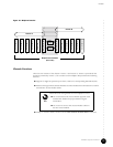
The G10 CMTS chassis is constructed of plated sheet metal. It fits into a 19-inch equipment
rack that complies with EIA standard RS-310-C. You can install the chassis into a 23- inch EIA
rack by attaching additional mounting brackets to the sides of the chassis. Additional rail and
bracket mounting holes are provided to support installation into nonstandard racks.
Threaded nuts for chassis ground are located on the lower right side of the chassis near the
rear. One ESD jack for wrist straps is located in the front upper center (see Figure 4 on
page 11).
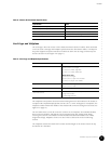
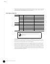
Table 1: Chassis Physical Specifications
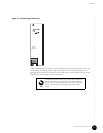
You cannot use an HFC Connector Module in a version 2
chassis if you are also using a NIC Module.
Specification Value
Height 578 mm (22.8 in., 13 U)
Width 480 mm (18.9 in.), excluding mounting brackets
Depth 483 mm (19.0 in.)
Weight 36 kg (80 lb) empty
64 kg (140 lb) fully populated