


•
•
•
•
•
•
•
•
•
•
•
•
•
•
•
•
•
•
•
•
•
•
•
•
•
•
•
•
•
•
•
•
•
•
•
•
•
•
•
•
•
•
•
•
•
•
•
•
•
•
•
•
•
•
•
•
•
•
Connect the Power and Perform Initial Configuration
Power On and Configure the PC
127
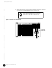
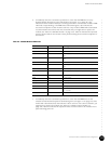
described in step 8 (see Figure 17 on page 49). Table 44 indicates the expected status of
all the LEDs on the NIC Access Module’s rear panel following power-on. If the
OPERATION LED is not illuminated green, the NIC Access Module is considered faulty
and you might have to replace it (see the “Remove a NIC Access Module” on page 170).
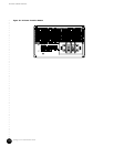
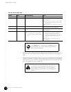
Table 44: NIC Access Module LED Status
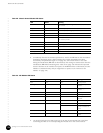
Power On and Configure the PC
1. Power on the personal computer (PC) attached to the serial port of the Chassis Control
Module.
2. Launch your asynchronous terminal emulation application (such as Microsoft Windows
Hyperterminal), and establish a direct connection. Configure the port settings as follows:
! Bits per second: 9600
! Data bits: 8
! Parity: None
! Stop bits: 1
! Flow control: None
LED Post-initialization Status Meaning
POWER Green Power is applied.
OPERATIONAL Green Successful initialization.
INT FAULT Off No internal failure.
EXT FAULT Off No external failure.
Amber One or more of the FE or GE ports is
enabled, but unused.
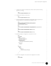
Before you replace any module that appears to be faulty
based on its LED status, contact Juniper Networks
customer support for technical assistance.