


Chassis
•
•
•
•
•
•
•
•
•
•
•
•
•
•
•
•
•
•
•
•
•
•
•
•
•
•
•
•
•
•
•
•
•
•
•
•
•
•
•
•
•
•
•
•
•
•
•
•
•
•
•
•
•
•
•
•
•
•
JUNOSg 3.0 G10 CMTS Hardware Guide
22
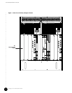
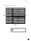
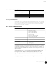
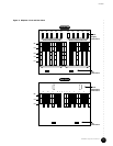
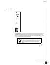
The modules in the card cage use the P1 through P5 connectors of the midplane (see Figure 9
on page 23). The power supplies use connectors PS1 through PS10. Fan trays and power
transition modules also connect to the midplane.
Connectors P3 through P5 provide the pass-through interconnection between the modules in
the front and rear of the chassis. Connectors P1 and P2 support the cPCI bus. The major
signals carried by the connectors are described in Table 4.
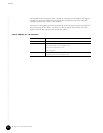
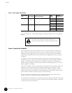
Table 4: Midplane P1 – P5 Connectors
Connector Function
P1 and P2 cPCI bus
P3 I
2
C bus
Ethernet to/from HFC Connector Module or SIM
Synchronization and reference clocks
Power and ground
P4 and P5 RF signals to HFC Connector Module or SIM
IF signals from HFC Connector Module or SIM