


G10 CMTS Hardware Overview
•
•
•
•
•
•
•
•
•
•
•
•
•
•
•
•
•
•
•
•
•
•
•
•
•
•
•
•
•
•
•
•
•
•
•
•
•
•
•
•
•
•
•
•
•
•
•
•
•
•
•
•
•
•
•
•
•
•
JUNOSg 3.0 G10 CMTS Hardware Guide
16
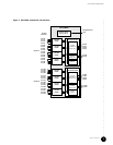
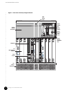
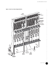
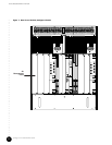
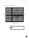
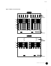
Following is a brief explanation of each feature shown in Figure 4 through Figure 7:
Front Features ! DOCSIS Module—Module that contains the Broadband Cable Processor ASIC and resides
between the network-side interface (NSI) and the hybrid fiber/coax (HFC) interface.
! NIC Module—Module that provides the Gigabit Ethernet interface and the Fast Ethernet
switching functions for the network-side interface.
! Chassis Control Module—Module that performs management and monitoring functions.
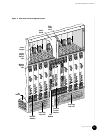
! Module ejector rail—Rail into which a module’s ejector tabs fit when a module is
installed in a slot.
! ESD strap connector—Location where you can insert an ESD ground strap.
! Air intake—Slotted openings along the front (removable) and sides of the chassis where
air is drawn into the chassis for cooling the installed modules and power supplies.
! Air intake faceplate—Slotted removable panel that covers the two front fan trays.
! Air intake faceplate clip—Retainer clip used to mount the air intake faceplate.
! Front fan tray—Fan assembly that forces air upward through the front of the chassis.
! Front fan tray LED—LED that shows the status of the front fan tray.
! Power supply ejector rail—Rail into which the power supply ejector tabs fit when a
power supply is installed in a bay.
! Midplane—Passive electrical interconnecting device for all modules in the chassis.
! Air management module—Module installed in an unused module slot to redirect the air
flow through the chassis and to reduce EMI emissions.
! Card guide—Used to align a module or power supply while it is being inserted into its
slot or bay.
! Power supply—Converts AC or DC power supplied through the power transition modules
into the DC voltages required by the modules.
! Power supply faceplate—Panel along the top of the chassis that covers the power
supplies.
! Power supply faceplate clip—Retainer clip used to mount the power supply faceplate.
! Power supply bay—Chassis bay in which a single hot-swappable power supply is
inserted.
! Power supply filler panel—Panel covering an empty power supply bay.
! Cable channel—Channel through the top of the chassis that is used to route the network
cables from the rear of the chassis to the front.
! Cable guide—Guide used to route the network cables between the cable channel and the
lower opening in the power supply faceplate.