


•
•
•
•
•
•
•
•
•
•
•
•
•
•
•
•
•
•
•
•
•
•
•
•
•
•
•
•
•
•
•
•
•
•
•
•
•
•
•
•
•
•
•
•
•
•
•
•
•
•
•
•
•
•
•
•
•
•
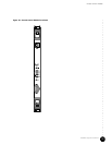
Hardware Component Overview
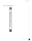
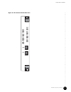
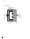
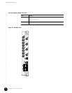
NIC Module
47
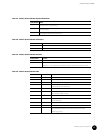
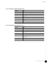
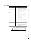
Table 21: NIC Module LEDs
LED Color Function
Pull Red On—Module software is in a safe state; module can be
removed.
LED is on during power up and off during normal
operation.
0 through 23 Green On—Successful link of the corresponding Ethernet
interface.
FLASHING—Activity on corresponding channel.
LEDs are off during power up.
GB0
GB1
Green On—Successful link of corresponding Gigabit Ethernet
interface.
LED is off during power up.
CLK Green Not used.
LED is on during power up and off during normal
operation.
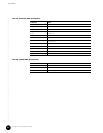
PWR Green On—Power is applied to the module.
LED is on during power up.
RTM Green On—Continuity is established with NIC Access Module
(Rear Transition Module).
LED is on during power up.
OK Green On—Successful initialization of module completed.
LED is off during power up and on after initialization is
completed.
EXT FLT Amber On—One or more of the FE or GE ports is enabled, but
unused.
LED is on during power up.
INT FLT Amber On—Failure detected in the module.
LED is on during power up.
Hot SWP Blue On—Module is ready to be removed. Illuminates after the
ejector release is pressed. During hot insertion, LED is on
until ejectors are locked.
Off during power up.
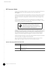
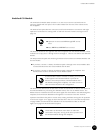
When the single-mode (long-range—80 km) GBIC module
is used in the NIC Module and there is no link activity on
the Gigabit Ethernet port, the LEDs GB0 and GB1 might
dimly flicker. This is normal.