


•
•
•
•
•
•
•
•
•
•
•
•
•
•
•
•
•
•
•
•
•
•
•
•
•
•
•
•
•
•
•
•
•
•
•
•
•
•
•
•
•
•
•
•
•
•
•
•
•
•
•
•
•
•
•
•
•
•
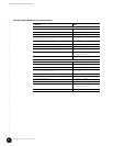
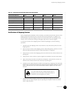
Prepare the Site
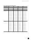
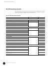
G10 CMTS Installation Checklist
91
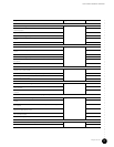
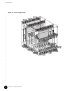
Install a Chassis Control Module and a Hard Disk Module
Remove the air management module where the Chassis Control Module will be inserted page 108
Release the ejectors, align to the card guides, insert the Chassis Control Module, and
close the ejectors
Tighten the self-contained screws
Remove the air management panel where the Hard Disk Module will be inserted
Release the ejectors, align to the card guides, insert the Hard Disk Module, and close the
ejectors
Tighten the self-contained screws
Install a NIC Module and a NIC Access Module
Remove the air management module where the NIC Module will be inserted page 108
Release the ejectors, align to the card guides, insert the NIC Module, and close the
ejectors
Tighten the self-contained screws
Remove the air management panel where the NIC Access Module will be inserted
Release the ejectors, align to the card guides, insert the NIC Access Module, and close
the ejectors
Tighten the self-contained screws
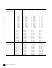
Cable an HFC Connector Module or SIM
Determine how the cable plant nodes will be connected to the downstream and
upstream ports of the module
page 109
Connect each of the four downstream ports to its respective node
Connect each of the four upstream ports to its respective node
Dress all cables appropriately
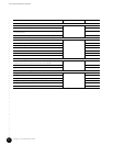
Cable a Chassis Control Module
Thread the Ethernet cable through the cable channel from the rear of the chassis page 113
Connect the RJ-45 connector of the Ethernet cable to the Eth0 port on the Chassis
Control Module
Connect the other end of the Ethernet cable to its respective network equipment in the
headend
Cable a NIC Module and a NIC Access Module (if applicable)
Thread the network cables through the cable channel from the rear of the chassis page 113
Connect each of the two Gigabit Ethernet network cables to the ports on the NIC
Module
Connect the other ends of the network cables to their respective network equipment in
the headend
Connect the RJ-21 end of the NIC Access Module cable into the NIC Access Module and
tighten the cable retainer screws
Connect eight RJ-45 connectors of the NIC Access Module cable to a maximum of four
HFC Connector Module
Dress all cables appropriately
Attach a PC to the Chassis Control Module
Connect the serial cable to the COM port on the Chassis Control Module page 119
Connect the other end of the serial cable to the serial port on the PC
Step Page Number Completion Status