


•
•
•
•
•
•
•
•
•
•
•
•
•
•
•
•
•
•
•
•
•
•
•
•
•
•
•
•
•
•
•
•
•
•
•
•
•
•
•
•
•
•
•
•
•
•
•
•
Hardware Component Overview
19
Chapter 2
Hardware Component Overview
This chapter provides an overview of the G10 CMTS hardware components:
! Chassis on page 19
! DOCSIS Module on page 29
! Chassis Control Module on page 37
! NIC Module on page 42
! Chassis Rear Modules on page 48
Chassis
This section discusses the following characteristics of the G10 CMTS chassis components:
! Physical Characteristics on page 20
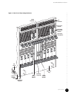
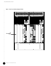
! Card Cage and Midplane on page 21
! Chassis Versions on page 25
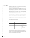
! Power Supplies on page 26
! Power Transition Modules on page 28
! Cooling and Fans on page 29
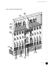
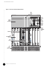
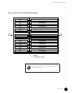
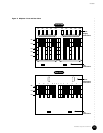
The chassis is a rack-mountable, 19-inch wide, 13 U high housing that contains the modules,
power supplies and fans. The chassis accepts CompactPCI standard modules that conform to
dimensions specified in IEEE Standard 1101.1-1998. The use of a midplane as the
interconnecting device allows modules to be installed from both the front and rear of the
chassis.
See Figure 4 on page 11 and Figure 6 on page 13 for illustrations of the front and rear of a
fully populated chassis.