


•
•
•
•
•
•
•
•
•
•
•
•
•
•
•
•
•
•
•
•
•
•
•
•
•
•
•
•
•
•
•
•
•
•
•
•
•
•
•
•
•
•
•
•
•
•
•
•
•
•
•
•
•
•
•
•
•
•
Install the CMTS
Rack Mounting
97
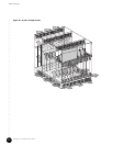
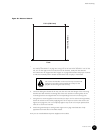
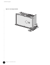
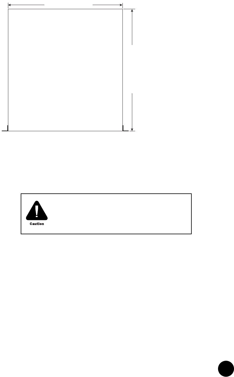
Figure 26: Bottom of Chassis
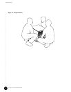
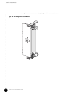
5. When lifting the chassis, we recommend that you follow the safety precautions listed in
the “Safety Precautions” on page 68. Using a lift (or at least three installers—one on the
left, one on the right, and one in the front of the chassis), slowly lift and slide the
G10 CMTS onto the equipment shelf. Figure 27 on page 98 illustrates the proper manner
in which to manually lift the chassis such that the risk of injury is minimized.
6. Continue sliding the chassis all the way into the rack until the flanges of the mounting
brackets are flush with the mounting rails of the rack and the mounting holes in the
mounting brackets are aligned with the corresponding holes in the mounting rails.
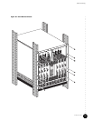
7. Using the #12 screws supplied in the accessory kit (up to six for each mounting bracket),
fasten the chassis to the rack by applying 30 in-lb of torque to each of the screws (see
Figure 28 on page 99). Do not completely tighten any screw to its torque specification
until all 12 screws are inserted.
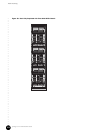
8. Attach the ground strap to earth ground. Figure 29 on page 100 illustrates a fully
populated rack with three G10 CMTS chassis.
Now you can install additional power supplies and modules.
17.3 in (439.4 mm)
Front
18.6 in (472.6 mm)
Do not use the handles on the rear fan tray to assist with
lifting the G10 CMTS. These handles are solely for the
purpose of removing the rear fan tray.