


•
•
•
•
•
•
•
•
•
•
•
•
•
•
•
•
•
•
•
•
•
•
•
•
•
•
•
•
•
•
•
•
•
•
•
•
•
•
•
•
•
•
•
•
•
•
•
•
•
•
•
•
•
•
•
•
•
•
System Overview
G10 CMTS Hardware Overview
17
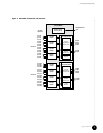
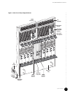
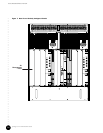
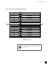
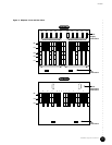
Rear Features ! HFC Connector Module—Module that functions as the DOCSIS Module’s physical access
to both the NSI and the HFC interfaces on the rear of the chassis.
! Switched I/O Module—Provides the same functions as an HFC Connector Module, but
provides four additional upstream F-connectors for the HFC cabling.
! NIC Access Module—Module that provides the network connections between the NIC
Modules and the HFC Connector Modules.
! Hard Disk Module—Contains the system nonvolatile memory implemented as a hard
disk. This module is installed opposite the Chassis Control Module.
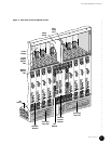
! Rear fan tray—Fan assembly that forces air upward through the rear of the chassis.
! Rear fan tray LED—LED that shows the status of the rear fan tray.
! Air management panel—Panel installed over an unused module slot to redirect the air
flow through the chassis and to reduce EMI emissions.
! Air exhaust—Panel along the top and rear of the chassis where air is expelled from the
chassis for cooling.
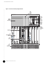
! AC power transition module—Rear module that distributes the externally supplied AC
power to the midplane.
! AC power receptacle—AC power cord receptacle on AC power transition module.
! AC power switch—AC power On/Off switch that resides on the AC power transition
module.
! DC power transition module—Rear module that distributes the externally supplied DC
power to the midplane.
! DC power receptacle—DC power cord terminal block on DC power transition module.
! Chassis ground nuts—Location where the earth ground connection to the chassis is
made.