


•
•
•
•
•
•
•
•
•
•
•
•
•
•
•
•
•
•
•
•
•
•
•
•
•
•
•
•
•
•
•
•
•
•
•
•
•
•
•
•
•
•
•
•
•
•
•
•
Connect the Power and Perform Initial Configuration
123
Chapter 6
Connect the Power and Perform Initial Configuration
It is assumed that you have followed the installation procedures described in “Install the
CMTS” on page 93 prior to performing the procedures presented in this chapter.
This chapter discusses the following topics:
! Power On the G10 CMTS on page 123
! Power On and Configure the PC on page 127
! Perform Initial Software Configuration on page 128
Power On the G10 CMTS
The following procedure defines the power-on procedure and the expected state of the LEDs
on the power supplies, fan trays, and module panels after the CMTS is powered on.
1. Ensure that the power sources connected to the power transition modules are switched
on.
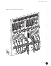
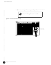
2. If the CMTS is AC powered, press the rocker switch on each AC power transition module
to the on (|) position (see Figure 38 on page 120). There is no requirement that the two
power switches be turned on in any particular order. If the G10 CMTS is DC powered, the
system will be powered up when the DC power transition modules have been connected
to the DC power sources.
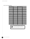
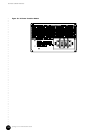
3. Remove the power supply faceplate by pulling the flanges on each side of the faceplate
away from the chassis until the faceplate ball studs are removed from the power supply
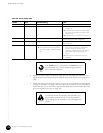
faceplate clips. Ensure that all power supplies are operating normally by checking that
the Power LED is illuminated green and the Fault LED is not illuminated. If this is not the
case, see Table 40 for a list of other LED combinations and the corresponding action to
take.
Ensure that you have read and taken the safety precautions
in “Prepare the Site” on page 67 prior to powering on the
G10 CMTS.