•
•
•
•
•
•
•
•
•
•
•
•
•
•
•
•
•
•
•
•
•
•
•
•
•
•
•
•
•
•
•
•
•
•
•
•
•
•
•
•
•
•
•
•
•
•
•
•
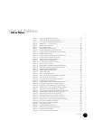
List of Tables
xi
List of Tables
List of Tables
Table 1: Chassis Physical Specifications ...........................................................20
Table 2: Chassis Environmental Specifications.................................................21
Table 3: Card Cage and Midplane Specifications ..............................................21
Table 4: Midplane P1 – P5 Connectors.............................................................22
Table 5: Midplane Configuration ......................................................................24
Table 6: Power Supply LEDs.............................................................................26
Table 7: Power Supply Specifications ..............................................................28
Table 8: DOCSIS Module Physical Dimensions.................................................36
Table 9: DOCSIS Module Operational Characteristics .......................................36
Table 10: DOCSIS Module LEDs .........................................................................36
Table 11: Chassis Control Module Physical Dimensions .....................................41
Table 12: Chassis Control Module Connectors....................................................41
Table 13: Chassis Control Module Switches........................................................41
Table 14: Chassis Control Module LEDs..............................................................41
Table 15: NIC Module Physical Dimensions........................................................44
Table 16: NIC Module Connectors......................................................................44
Table 17: Single-Mode, Long-Range GBIC Specifications.....................................45
Table 18: Single-Mode, Midrange GBIC Specifications ........................................45
Table 19: Multimode GBIC Specifications ...........................................................46
Table 20: 1000BT GBIC Specifications................................................................46
Table 21: NIC Module LEDs................................................................................47
Table 22: NIC Access Module LEDs ....................................................................48
Table 23: HFC Connector Module Fast Ethernet LEDs........................................50
Table 24: SIM Fast Ethernet Port LEDs...............................................................54
Table 25: G10 CMTS Environmental Specifications ............................................72
Table 26: Coaxial Cable Requirements...............................................................75
Table 27: RF Plant/HFC Environment Characterization ......................................76
Table 28: Existing DOCSIS Service Characterization...........................................77
Table 29: Upstream CMTS Parameter Characterization......................................78
Table 30: Downstream CMTS Parameter Characterization .................................80
Table 31: Upstream Frequency Spectrum Utilization..........................................81
Table 32: Pre-Installation Requirement Summary Checklist...............................82
Table 33: Average Noise Spectrum Analyzer Settings.........................................83
Table 34: Peak Noise Spectrum Analyzer Setup..................................................84
Table 35: Existing DOCSIS Service Characterization...........................................86
Table 36: Upstream CMTS Parameter Characterization......................................87
Table 37: Downstream CMTS Parameter Characterization ................................89
Table 38: G10 CMTS Installation Checklist..........................................................90
Table 39: NIC Access Module Wiring Plan........................................................118
Table 40: Power Supply LEDs...........................................................................124
Table 41: DOCSIS Module LED Status...............................................................125
Table 42: Chassis Control Module LED Status...................................................126
Table 43: NIC Module LED Status.....................................................................126
Table 44: NIC Access Module LED Status..........................................................127


